
Are Transition Losses Degrading Your RF Network? The Function and Application of Waveguide to Coaxial Adapters Explained
Bridge the gap between waveguide and coaxial systems. Learn how waveguide to coaxial adapters ensure TE10 to TEM mode conversion and protect signal integrity.
Are Transition Losses Degrading Your RF Network? The Function and Application of Waveguide to Coaxial Adapters Explained
In the complex architecture of modern microwave systems, engineers are constantly forced to bridge two entirely different worlds. On one side, you have the Waveguide—a rigid, hollow metal structure capable of handling massive power with ultra-low loss, but entirely inflexible. On the other side, you have the Coaxial Cable—highly flexible, broadband, and universally used to connect sensitive transceivers, signal generators, and Vector Network Analyzers (VNAs).
At some point in your 5G mmWave base station, satellite earth station, or EMC testing laboratory, these two transmission mediums must meet. But you cannot simply solder a wire to a metal pipe and expect your signal to survive.
When high-frequency electromagnetic energy transitions between a waveguide and a coaxial line, it faces a violent shift in impedance and electromagnetic field structure. If this transition is not managed with absolute precision, the result is severe signal reflection (high VSWR), unacceptable insertion loss, and potentially catastrophic damage to your sensitive test equipment.
To solve this critical engineering bottleneck, system integrators rely on a highly specialized, precision-machined component: the Waveguide to Coaxial Adapter.
In this comprehensive guide, we will explore the complex physics behind mode conversion, detail the critical industry applications of these adapters, and demonstrate how partnering with an agile, industrial-grade manufacturer can protect your signal integrity while keeping your project timelines strictly on track.
The Physics of the Transition: How Does the Adapter Function?
To understand the function of a waveguide to coaxial adapter, we must look at the fundamental differences in how electromagnetic waves travel through these two mediums.
- In a Coaxial Cable: The electromagnetic wave travels in a TEM (Transverse Electromagnetic) mode. The electric field radiates radially between the solid center conductor and the outer shield.
- In a Rectangular Waveguide: There is no center conductor. The wave travels in a TE10 (Transverse Electric) mode, where the electric field spans across the hollow space between the broad walls of the waveguide.
The primary function of the adapter is Mode Conversion. It must seamlessly transform the TEM mode of the coaxial cable into the TE10 mode of the waveguide (or vice versa) without allowing the energy to reflect backward.
Inside the adapter, the center pin of the coaxial connector extends into the hollow cavity of the waveguide. This pin acts as a tiny, precisely tuned antenna (a probe). When a signal enters from the coaxial side, this probe radiates the electric field into the waveguide cavity, exciting the TE10 mode. A metallic "shorting plate" (the back wall of the adapter) is positioned exactly at a calculated distance behind the probe to reflect the radiating energy forward, ensuring maximum power transfer down the waveguide.
The characteristic impedance of a standard coaxial cable is 50 Ohms. However, the impedance of a waveguide varies with frequency and is typically much higher (often between 300 and 500 Ohms). If an adapter is poorly machined, this massive impedance mismatch will cause a severe Voltage Standing Wave Ratio (VSWR) spike. A premium adapter utilizes precision-machined tuning steps or a carefully calculated probe depth to ensure a flawless 50-Ohm match across the entire operating frequency band.
Right-Angle vs. End-Launch Adapters
Depending on your mechanical space constraints and system layout, waveguide to coaxial adapters are manufactured in two primary configurations:
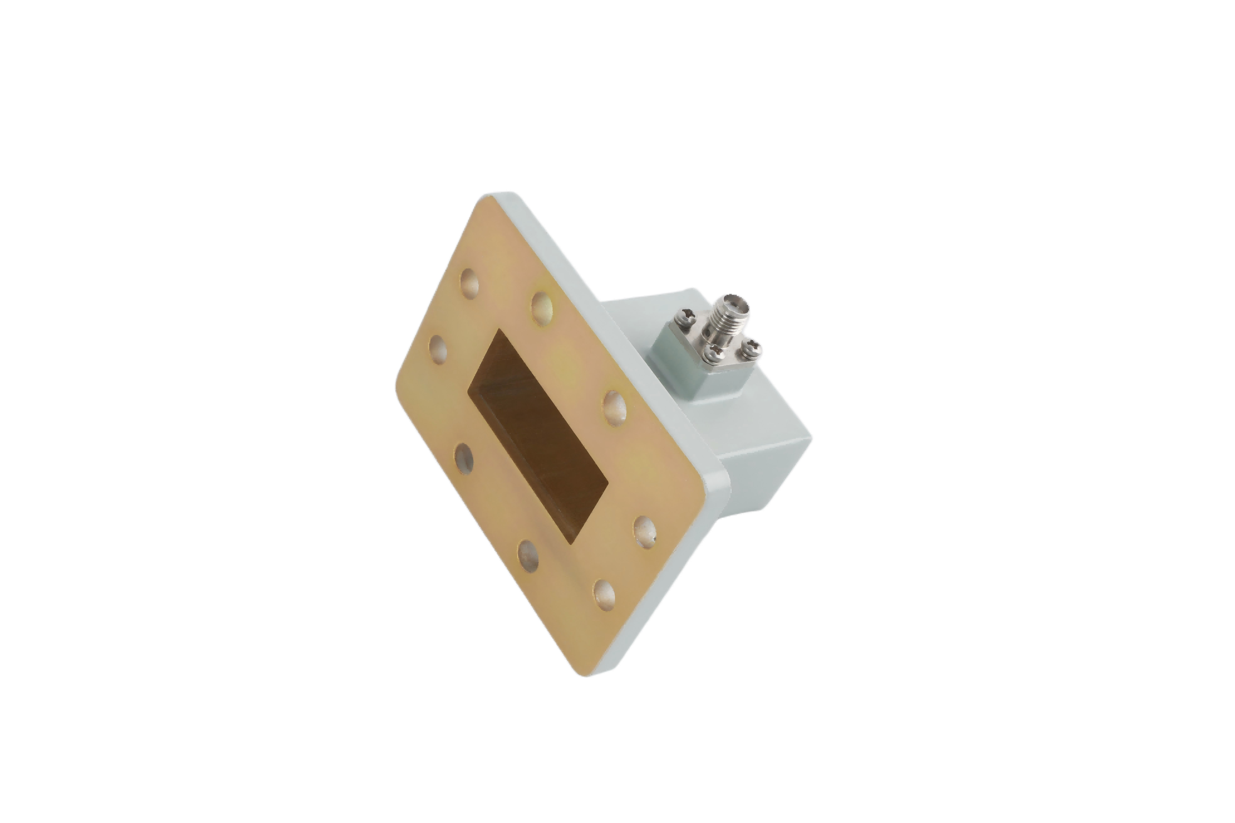
1. Right-Angle Adapters
This is the most common configuration. The coaxial connector is mounted on the broad wall of the waveguide, perpendicular (at a 90-degree angle) to the direction of the waveguide signal flow.
- The Advantage: Highly efficient mode conversion and excellent VSWR performance. It is the industry standard for most test and measurement applications.
2. End-Launch (In-Line) Adapters
In this configuration, the coaxial connector is mounted at the very end of the waveguide, parallel to the signal flow. The transition happens in a straight line.
- The Advantage: Ideal for environments where mechanical space is severely restricted, such as inside densely packed UAV payloads, phased array radar modules, or compact 5G transceivers where a right-angle connector would protrude too far.
Critical Industry Applications for Waveguide to Coaxial Adapters
These adapters are the critical connective tissue in any RF architecture that requires both high-power transmission and flexible signal processing. Key applications include:
| Industry | Mission-Critical Application |
|---|---|
| Test & Measurement (EMC Labs) | Connecting highly sensitive Vector Network Analyzers (VNAs) or spectrum analyzers (which use coaxial interfaces) to rigid waveguide components (like horn antennas or directional couplers) for calibration and immunity testing. |
| Satellite Communications (Satcom) | Bridging the gap between the coaxial output of a Low Noise Block downconverter (LNB) or a Block Upconverter (BUC) and the rigid waveguide feed network of the satellite dish. |
| 5G mmWave Telecommunications | Transitioning the high-frequency signal from the coaxial output of a transceiver module into the waveguide antenna array, minimizing dielectric loss in the backhaul network. |
| Defense & Radar Systems | Injecting a low-power coaxial test signal from a local oscillator into a high-power waveguide radar system for diagnostic purposes. |
While waveguides can handle massive amounts of power, coaxial connectors cannot. An N-Type connector might handle a few hundred watts, but an SMA or 2.92mm connector will melt under high continuous wave (CW) power. When designing your system, remember that the coaxial connector is always the weakest link in power handling. Never push more power through the adapter than the specific coaxial connector is rated for!
Overcoming Supply Chain Fragility with Agile Manufacturing
Designing a flawless RF transition is a significant engineering achievement. However, the true challenge for system integrators today is securing these precision components on time to meet strict project deadlines.
For decades, the RF industry has relied on a handful of legacy Western manufacturers. While their quality is established, their rigid, bureaucratic supply chains often result in agonizing 16 to 24-week lead times. When you are deploying a new satellite earth station or setting up a critical EMC test bench, waiting half a year for a simple WR-90 to SMA adapter is unacceptable. It stalls projects, frustrates stakeholders, and delays your time-to-market.
You need a partner who matches your engineering rigor with manufacturing agility.
At AO Microwave, we redefine industrial-grade reliability. We manufacture premium waveguide to coaxial adapters, directional couplers, and RF cable assemblies with uncompromising precision. By combining advanced CNC machining and rigorous impedance tuning with an agile, streamlined manufacturing process, we deliver the ultra-low VSWR and pristine signal integrity your systems demand—without the crippling lead times of legacy brands. We empower your engineering teams to stay on schedule, keep your networks online, and execute with confidence.
Conclusion: Bridge the Gap with Absolute Precision
In the high-stakes world of microwave engineering, a waveguide to coaxial adapter is far more than a simple mechanical fitting; it is a highly engineered electromagnetic bridge. By seamlessly converting TE10 waveguide modes to TEM coaxial modes and perfectly matching the impedance, these adapters protect your sensitive test equipment and ensure pristine signal integrity across your entire network.
By prioritizing critical specifications like VSWR and connector power limits, and by partnering with an agile manufacturer dedicated to industrial-grade excellence, you can build a resilient, high-performance RF system that is delivered on time, every time.
Ready to Optimize Your RF Transitions?
Don't let poor impedance matching degrade your signal, and don't let rigid supply chains delay your project launches. Whether you need precision Right-Angle Adapters for a VNA test bench or compact End-Launch Adapters for a 5G transceiver, AO Microwave delivers the reliability and responsiveness you need.
Contact our engineering team today for a technical consultation, and let us help you build a resilient, perfectly matched RF architecture.