
Are You Losing Signal in Your RF System? Why the Essential Straight Waveguide Section Matters More Than You Think?
Are you losing signal in your RF system? Discover why high-quality straight waveguide sections are essential for low insertion loss and how to reduce BOM costs.
Are You Losing Signal in Your RF System? Why the Essential Straight Waveguide Section Matters More Than You Think?
When engineers design a state-of-the-art RF microwave system—whether it is a 5G mmWave base station, a commercial satellite earth station, or a high-power EMC testing chamber—they naturally focus their attention on the "glamorous" active components. They obsess over the High-Power Amplifiers (HPAs), the precision of the directional couplers, and the gain of the horn antennas.
But how does the electromagnetic energy actually travel between these expensive components? It travels through the unsung hero of the microwave world: the Straight Waveguide Section.
Because a straight waveguide looks like nothing more than a simple hollow metal pipe, it is often treated as an afterthought in the procurement process. However, this is a dangerous and costly mistake. If a straight waveguide section is poorly manufactured, it will introduce severe insertion loss, trigger Voltage Standing Wave Ratio (VSWR) spikes, and cause passive intermodulation (PIM). You could spend tens of thousands of dollars on a top-tier amplifier, only to have your signal degrade before it even reaches the antenna.
With the global RF and microwave components market expanding rapidly to support Low Earth Orbit (LEO) satellite constellations and advanced UAV data links, optimizing your transmission lines is critical. In this comprehensive guide, we will explore why the essential straight waveguide section is the backbone of your RF system, the physics behind its manufacturing, and how you can source high-quality industrial-grade sections without blowing your project budget.
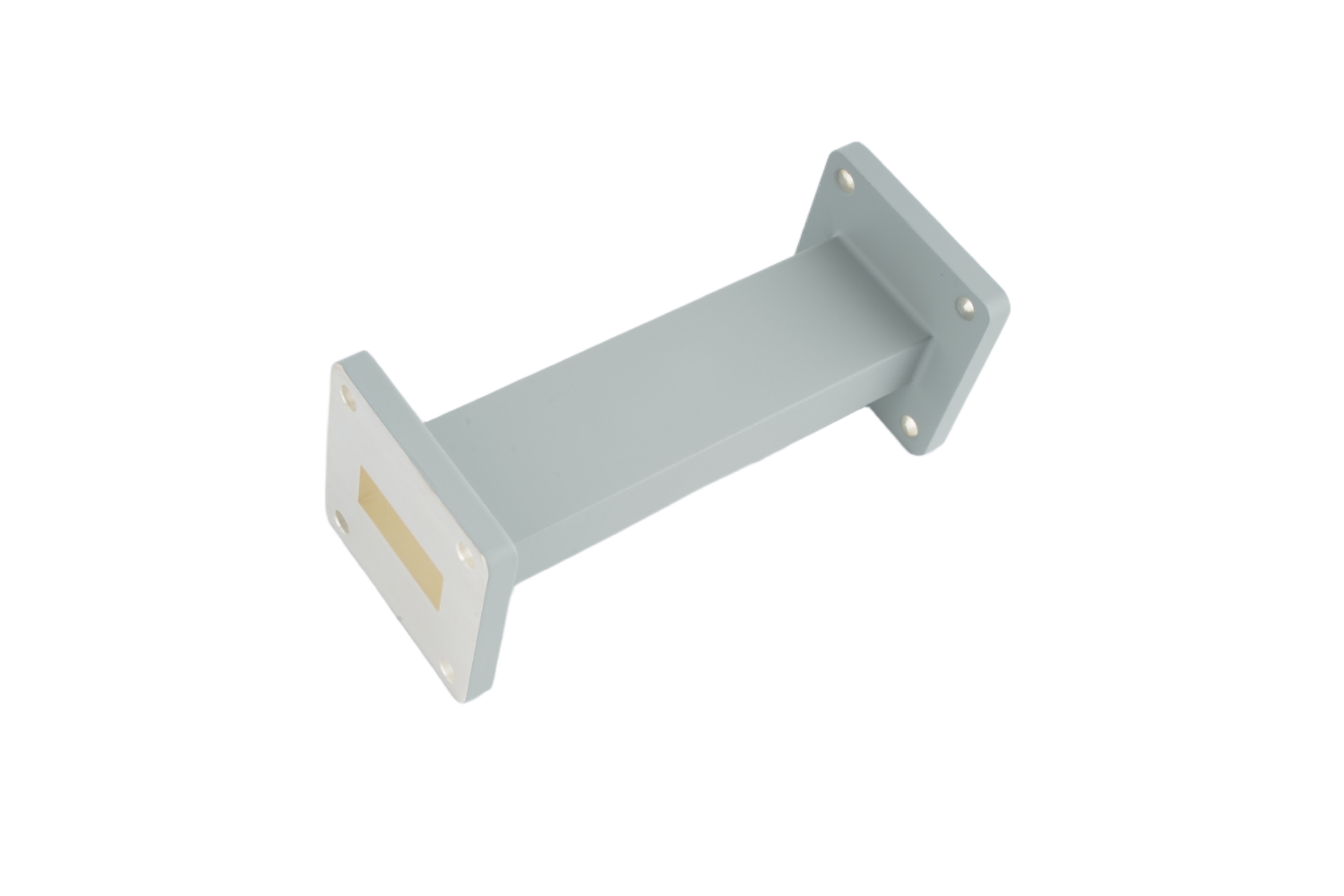
What Is a Straight Waveguide Section?
A straight waveguide section is exactly what it sounds like: a linear, hollow metallic tube used to guide high-frequency electromagnetic waves (typically from 1 GHz up to 100+ GHz) from one point to another. Unlike coaxial cables, which use a center conductor and a solid dielectric, waveguides use the air (or pressurized gas) inside the tube as the dielectric medium.
They are manufactured to strict Electronic Industries Alliance (EIA) standards, denoted by the "WR" (Waveguide Rectangular) prefix. For example, a WR-90 straight section is designed specifically for X-band frequencies (8.2 to 12.4 GHz), while a WR-28 section is used for Ka-band (26.5 to 40.0 GHz).
Why "Simple" Doesn't Mean "Easy": The Physics of Straight Waveguides
To understand why you cannot just use any piece of metal tubing for RF transmission, we must look at the physics of high-frequency electromagnetic waves.
1. The Skin Effect and Internal Surface Finish
At microwave frequencies, alternating current does not flow through the entire cross-section of the metal. Instead, it is pushed to the extreme outer layer—the "skin"—of the inner waveguide wall. In the Ku or Ka bands, this skin depth is measured in mere micrometers.
If the internal surface finish of the straight waveguide is rough (due to cheap extrusion or poor milling), the electrical path becomes longer and more resistive. This drastically increases Insertion Loss. A premium straight waveguide section must have a mirror-like internal finish to ensure the wave glides through with near-zero resistance.
2. Dimensional Tolerances and VSWR
A waveguide acts as a high-pass filter, and its cutoff frequency is entirely dependent on its broad wall dimension (the 'a' dimension). If a manufacturer's tolerances are sloppy and the dimensions vary even slightly along the length of the straight section, the impedance of the waveguide will change. This impedance mismatch causes RF energy to reflect backward, creating a high VSWR (Voltage Standing Wave Ratio), which can overheat and destroy your transmitter.
3. Flange Precision: The Weakest Link
A straight waveguide is only as good as its connection points. If the flanges at either end of the section are not perfectly flat and perpendicular to the tube, microscopic air gaps will form when bolted to another component. At high power, these gaps cause severe RF leakage and internal arcing (sparking).
Key Industry Applications for Straight Waveguide Sections
Because they offer ultra-low loss and massive power handling capabilities compared to coaxial cables, straight waveguide sections are the mandatory transmission medium in several critical industries:
- Satellite Earth Stations (Satcom): Used to connect the indoor High-Power Amplifiers (HPAs) to the outdoor antenna feed horn, often requiring long, continuous straight runs to minimize uplink signal loss.
- EMC / EMI Testing Chambers: Used to route pure, high-power RF signals from the amplifier room into the anechoic chamber without introducing external noise or interference.
- Defense and Weather Radar: Handling the extreme peak power (often in megawatts) of radar pulses, where any internal arcing would cause catastrophic system failure.
- Medical Linear Accelerators (LINACs): Guiding high-power S-band microwaves to accelerate electrons for precision radiation therapy.
- 5G mmWave Telecommunications: Connecting transceivers to antennas in high-frequency backhaul systems where coaxial cables are simply too lossy.
3 Critical Specifications to Check Before Ordering
When procurement managers and engineers are sourcing straight waveguide sections, specifying the WR size is only the first step. To ensure system integrity, you must define the following three parameters:
1. Material Selection: Aluminum vs. Copper/Brass
The material you choose impacts weight, cost, and thermal performance.
- Aluminum (e.g., 6061-T6): Lightweight and cost-effective. It is the industry standard for aviation, UAV payloads, and large telecom tower installations where weight is a primary concern.
- Copper or Brass: Heavier and slightly more expensive, but offers superior electrical conductivity and thermal dissipation. It is the preferred choice for high-power continuous wave (CW) applications, such as EMC testing and medical equipment.
2. Flange Types
Ensure the flanges on your straight section perfectly match your mating equipment. Common types include:
- Cover Flange: A flat, smooth flange used for standard connections.
- Choke Flange: Contains a precisely machined groove designed to create an electrical short circuit at the joint, preventing RF leakage even if the mechanical seal isn't perfect.
- CPRG / CPRF: Contact Pressurizable Rectangular Grooved/Flat flanges, used when the waveguide system needs to be pressurized with dry air or gas to prevent high-power arcing.
3. Surface Treatment and Plating
To combat oxidation and improve conductivity (mitigating the skin effect), specify the correct plating. Silver plating is highly recommended for brass/copper waveguides operating at high frequencies, as silver has the highest electrical conductivity of any metal. For aluminum, a chromate conversion coating (like Iridite or Alodine) provides excellent corrosion resistance for outdoor telecom environments.
The "Aerospace-Grade" Trap: How to Optimize Your BOM Costs
Once engineers understand the precision required for a straight waveguide section, procurement teams often panic. There is a pervasive myth in the RF industry that to get a perfectly milled, low-loss waveguide, you must purchase ultra-expensive "aerospace-grade" components from legacy Western brands, often enduring 12 to 16-week lead times.
This is a massive drain on your project budget and timeline.
Unless your waveguide is literally being launched into deep space on a satellite payload, you do not need to pay the premium for aerospace-grade certification, deep-space outgassing tests, or exotic lightweight alloys. For the vast majority of terrestrial applications—including 5G telecom networks, commercial satellite earth stations, EMC testing labs, and defense radar—high-quality industrial-grade waveguide sections offer the exact same electrical performance at a fraction of the cost.
Conclusion: Build a Solid Foundation for Your RF Architecture
The straight waveguide section may not be the most complex component in your RF system, but it is undeniably the most essential. It is the highway upon which your valuable electromagnetic energy travels. By understanding the physics of the skin effect, prioritizing internal surface finishes, and selecting the correct materials and flanges, you can eliminate insertion loss and protect your amplifiers from VSWR spikes.
More importantly, building a robust RF architecture doesn't have to mean blowing your budget. By breaking free from the "aerospace-grade" myth and partnering with a reliable manufacturer of industrial-grade components, you can achieve world-class RF performance while keeping your supply chain agile and cost-effective.
Ready to Optimize Your RF Transmission Lines?
Don't let poorly manufactured straight waveguides degrade your signal and delay your system integration. Whether you need lightweight aluminum WR-75 sections for a UAV data link, or silver-plated brass WR-90 sections for a high-power EMC lab, AO Microwave has the industrial-grade solutions you need.
Contact our engineering sales team today for a technical consultation or a custom quote, and let us help you build a more reliable, cost-effective RF architecture.