
Are You Losing the Battle Against RF Interference? What Is a Waveguide Filter in Microwave Systems?
What is a waveguide filter? Learn how bandpass and low-pass waveguide filters eliminate 5G interference, handle high power, and reduce your BOM costs.
Are You Losing the Battle Against RF Interference? What Is a Waveguide Filter in Microwave Systems?
We live in an era of unprecedented electromagnetic crowding. With the explosive global rollout of 5G networks, the deployment of thousands of Low Earth Orbit (LEO) satellites, and the increasing complexity of defense radar systems, the RF spectrum has never been more congested. For RF engineers and system integrators, this congestion brings a massive headache: Signal Interference.
Imagine operating a critical C-band satellite earth station, only to have your sensitive receivers completely blinded by a nearby high-power 5G cell tower. Or picture an EMC testing chamber where out-of-band noise corrupts your multi-million-dollar compliance tests. When unwanted frequencies invade your transmission lines, signal integrity is destroyed, data is lost, and expensive amplifiers can be severely damaged.
To survive in this crowded spectrum, you need an uncompromising gatekeeper. You need a component that allows your desired frequencies to pass through with near-zero loss, while aggressively blocking everything else.
This is exactly where the Waveguide Filter becomes the most critical component in your microwave system.
But what exactly is a waveguide filter? Why is it vastly superior to standard coaxial or cavity filters at high frequencies? And how can procurement managers source these critical components without blowing their budgets on unnecessary "aerospace-grade" price tags? In this comprehensive guide, we will demystify waveguide filter technology and help you optimize your RF architecture.
What Is a Waveguide Filter? (The Physics Explained)
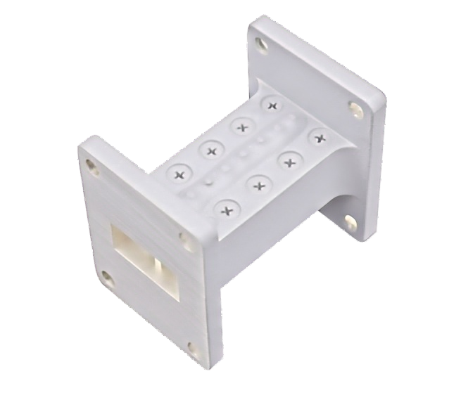
At its core, a waveguide filter is a passive RF/microwave component designed to control the flow of electromagnetic energy based on frequency. It is constructed using a section of hollow metallic waveguide (usually rectangular or circular) that has been internally modified with specific geometric structures—such as irises, posts, or corrugations.
These internal structures create resonant cavities. When an electromagnetic wave enters the filter, the physics of these cavities dictate how the wave behaves:
- Passband: Frequencies that match the resonant design of the cavities are allowed to pass through the filter with minimal resistance (low insertion loss).
- Stopband (Rejection): Frequencies outside the desired range are reflected back toward the source or absorbed, preventing them from traveling further down the line.
Why Choose Waveguide Filters Over Coaxial or PCB Filters?
If you are working at lower frequencies (like VHF or UHF), standard coaxial, lumped-element, or PCB-based filters work fine. However, as you move into microwave and millimeter-wave frequencies (X-band, Ku-band, Ka-band), these traditional filters fail miserably. Here are the three reasons waveguide filters dominate high-frequency systems:
1. Unmatched Q-Factor (Quality Factor)
The Q-factor measures a filter's selectivity. A high Q-factor means the filter can isolate a very narrow band of frequencies with incredibly steep rejection edges. Because waveguides have large internal volumes and highly conductive walls (minimizing skin effect resistance), they achieve Q-factors in the thousands—far exceeding what is possible with coaxial or microstrip filters.
2. Ultra-Low Insertion Loss
Every decibel of signal lost in a filter means you need a more expensive amplifier to compensate. Because waveguide filters use air (or pressurized gas) as their dielectric, there is zero solid dielectric loss. This allows the desired signal to pass through with insertion losses often well below 0.5 dB, preserving your precious signal strength.
3. Massive Power Handling
In defense radar or satellite uplinks, transmitters push hundreds or thousands of watts of RF power. Coaxial filters contain thin center conductors and solid Teflon dielectrics that will literally melt or arc under this stress. Waveguide filters, being robust hollow metal structures, can handle megawatts of peak power without breaking a sweat.
Common Types of Waveguide Filters in the Industry
Depending on what you need to block, engineers utilize different types of waveguide filters. The most common include:
| Filter Type | How It Works | Primary Application |
|---|---|---|
| Bandpass Filter (BPF) | Allows a specific range of frequencies to pass while blocking everything above and below it. | The most common type. Used in Satcom receivers to isolate the exact downlink frequency and block 5G/radar interference. |
| Low-Pass Filter (LPF) | Allows frequencies below a certain threshold to pass, blocking higher frequencies. Often uses a "corrugated" internal design. | Suppressing high-frequency harmonics generated by High-Power Amplifiers (HPAs) before they reach the antenna. |
| High-Pass Filter (HPF) | Allows frequencies above a certain threshold to pass. (Note: A standard waveguide naturally acts as a high-pass filter based on its cutoff frequency). | Eliminating low-frequency noise or ground-loop interference in wideband receiver systems. |
| Bandstop (Notch) Filter | Allows all frequencies to pass except for a specific, narrow band which is heavily attenuated. | Targeting and eliminating a specific known source of interference, such as a local jamming signal. |
Real-World Application: The 5G vs. Satcom Battle
To understand the true value of a waveguide filter, look no further than the ongoing global rollout of 5G networks. In many regions, 5G base stations operate in the C-band spectrum (e.g., 3.4 to 3.8 GHz). This sits dangerously close to the frequencies used by legacy C-band satellite earth stations (3.8 to 4.2 GHz).
Because 5G cell towers transmit at high power, their signals easily bleed into the Low Noise Block downconverters (LNBs) of nearby satellite dishes, completely saturating the receivers and knocking satellite networks offline.
The solution? System integrators install highly specialized Waveguide Bandpass Filters directly between the satellite antenna feed and the LNB. These filters are engineered to pass the 3.8-4.2 GHz satellite signals with near-zero loss, while providing massive rejection (often >60 dB or 70 dB) against the adjacent 5G signals. Without these filters, coexistence between 5G and Satcom would be physically impossible.
The "Aerospace-Grade" Trap: How to Optimize Your BOM Costs
When engineers realize they need the high Q-factor and power handling of a waveguide filter, procurement managers often brace for impact. There is a pervasive myth in the RF industry that to get a reliable, high-rejection filter, you must purchase ultra-expensive "aerospace-grade" components from legacy Western brands, often enduring 16 to 20-week lead times.
This is a massive drain on your project budget and timeline.
Unless your filter is literally being launched into deep space on a satellite payload, you do not need to pay the premium for aerospace-grade certification, deep-space outgassing tests, or exotic lightweight alloys. For the vast majority of terrestrial applications—including 5G telecom networks, commercial satellite earth stations, EMC testing labs, and defense radar—high-quality industrial-grade waveguide filters offer the exact same electrical performance at a fraction of the cost.
5 Critical Specs to Define When Ordering a Waveguide Filter
To ensure you get the exact filter your system needs, always provide your manufacturer with these five specifications:
- Center Frequency (f0) & Passband: The exact frequency range you want to let through (e.g., Passband: 10.95 to 11.70 GHz).
- Insertion Loss: The maximum acceptable signal loss within the passband (e.g., < 0.5 dB).
- Rejection (Stopband Attenuation): Which frequencies you need to block, and by how much (e.g., > 60 dB rejection at 10.50 GHz).
- Power Handling: The peak and average (CW) power the filter will be subjected to.
- Waveguide Size & Flange Type: Ensure the WR size (e.g., WR-75) and flange style (e.g., Cover, Choke, CPRG) match your existing system perfectly.
Conclusion: Protect Your Signal, Protect Your System
In today's congested RF environment, a waveguide filter is not just an accessory; it is a mandatory shield for your microwave system. By leveraging the physics of resonant cavities, these filters provide the ultra-low insertion loss, massive power handling, and steep rejection skirts necessary to eliminate interference and ensure pristine signal integrity.
More importantly, securing your RF architecture doesn't have to mean blowing your budget. By breaking free from the "aerospace-grade" myth and partnering with a reliable manufacturer of industrial-grade components, you can achieve world-class RF performance while keeping your supply chain agile and cost-effective.
Ready to Eliminate RF Interference in Your System?
Don't let 5G cross-talk or out-of-band noise compromise your network. Whether you need a custom Bandpass Filter for a Satcom receiver or a high-power Low-Pass Filter for a radar transmitter, AO Microwave has the industrial-grade solutions you need.
Contact our engineering sales team today for a technical consultation or a custom quote, and let us help you build a cleaner, more reliable RF architecture.