
Are You Risking Amplifier Failure? How Does Directional Waveguide Coupler Design Impact Your RF Applications?
Prevent amplifier failure with the right directional waveguide coupler. Explore coupler design principles, key RF applications, and how to reduce your BOM costs.
Are You Risking Amplifier Failure? How Does Directional Waveguide Coupler Design Impact Your RF Applications?
In the high-stakes world of RF and microwave engineering, ignorance is not bliss—it is expensive. If you are operating a high-power satellite earth station, a 5G mmWave base station, or a state-of-the-art EMC testing chamber, your system is constantly pushing massive amounts of electromagnetic energy through its transmission lines.
But what happens if a radome is damaged by a storm? What if an antenna feed degrades over time? The impedance mismatch will cause high-power RF energy to reflect backward down the waveguide, heading straight for your expensive High-Power Amplifier (HPA). Without a reliable way to detect this reflected power, your amplifier will suffer catastrophic failure, leading to weeks of system downtime and tens of thousands of dollars in replacement costs.
The ultimate insurance policy against this disaster is the directional waveguide coupler.
As the global microwave components market continues to surge—driven by the rapid expansion of Low Earth Orbit (LEO) satellite constellations and advanced defense radar systems—understanding the intricate design and specific applications of directional couplers is no longer optional. In this comprehensive guide, we will explore the physics behind waveguide coupler design, highlight their most critical industry applications, and reveal how procurement teams can optimize their Bill of Materials (BOM) without sacrificing system safety.

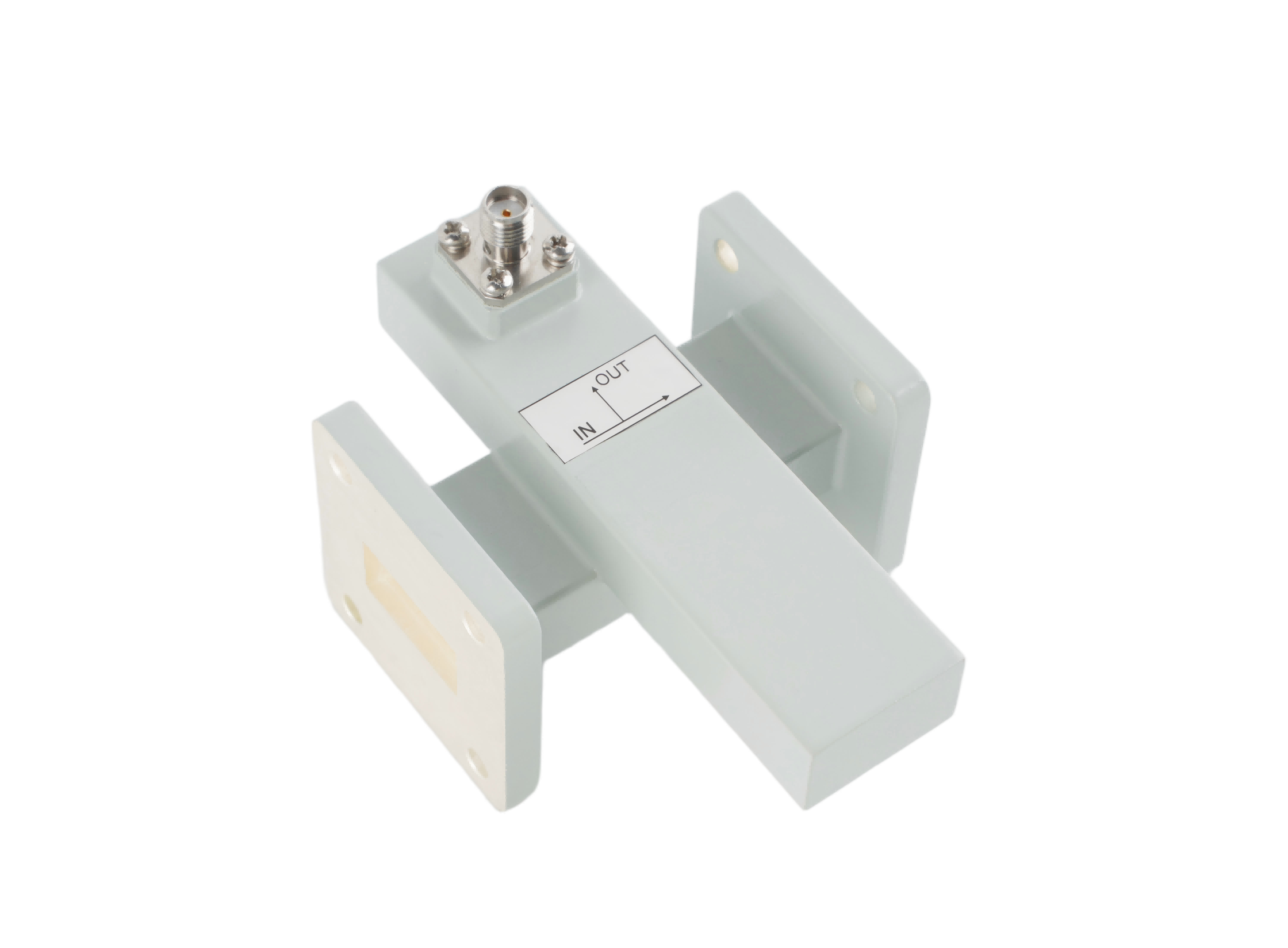
A well-designed directional waveguide coupler provides critical VSWR monitoring, protecting high-power RF amplifiers from catastrophic reflected energy.
The Anatomy of a Directional Waveguide Coupler: Design Principles
To appreciate how a directional coupler protects your system, we must look inside the metal casing. A directional waveguide coupler is a passive microwave device designed to sample a predetermined, tiny fraction of the RF power flowing through a main transmission line, routing it to a separate port for measurement.
The genius of its design lies in its ability to differentiate between the forward wave (traveling to the antenna) and the reflected wave (bouncing back). This is achieved through precise mechanical engineering and the physics of wave interference.
1. The Main Line and the Coupled Line
A standard coupler consists of two waveguides placed side-by-side or crossing each other. The primary waveguide (the Main Line) carries the high-power signal. The secondary waveguide (the Coupled Line) is where the sampling occurs. They share a common metallic wall.
2. The Coupling Apertures (Holes)
In the common wall separating the two waveguides, engineers machine specific holes or slots. The size, shape, and spacing of these apertures dictate the coupler's performance. In a high-precision Broadwall Coupler, there are typically multiple holes spaced exactly one-quarter wavelength (λ/4) apart.
3. Constructive and Destructive Interference
As the main electromagnetic wave passes these holes, a small amount of energy leaks into the secondary waveguide.
- Forward Direction: The leaked waves traveling in the same direction as the main signal are perfectly in phase. They add together (constructive interference) and exit the "Coupled Port," providing an accurate sample of the forward power.
- Reverse Direction: The leaked waves traveling in the opposite direction are out of phase due to the quarter-wavelength spacing. They cancel each other out (destructive interference). Any leftover energy is absorbed by a built-in matched termination load at the "Isolated Port."
Critical Design Specifications You Must Evaluate
When sourcing a directional waveguide coupler, system integrators must carefully evaluate three primary specifications to ensure the design matches the application:
- Coupling Factor (dB): This determines how much power is sampled. A 40 dB coupler means the sampled signal is 10,000 times weaker than the main signal. If you are transmitting 10 kW of power, the coupled port will safely output 1 Watt to your sensitive power meter.
- Directivity (dB): As mentioned, this is the measure of isolation between forward and reflected waves. High-end broadwall designs can achieve >40 dB directivity, making them essential for precise VSWR protection.
- Insertion Loss: The amount of power lost simply by adding the coupler to the main line. Because waveguides use air as a dielectric, a well-designed coupler will have near-zero insertion loss, ensuring maximum efficiency.
Key Industry Applications for Directional Couplers
Because of their ability to handle massive power levels with ultra-low loss, directional waveguide couplers are the backbone of monitoring systems across several high-tech industries.
1. Satellite Communications (Satcom & VSAT)
In satellite earth stations operating in the C, X, Ku, and Ka bands, transmitters must push high continuous wave (CW) power to reach satellites in orbit. Directional couplers are installed right before the antenna feed. They continuously monitor the forward power to ensure the signal is strong enough to penetrate atmospheric interference, while simultaneously monitoring reflected power to protect the Traveling Wave Tube Amplifiers (TWTAs) or Solid State Power Amplifiers (SSPAs).
2. EMC / EMI Testing Chambers
Electromagnetic Compatibility (EMC) testing requires generating intense, highly controlled RF fields to test the immunity of electronics (from pacemakers to automotive sensors). In these anechoic chambers, dual directional couplers are used to sample the exact forward power being fed to the horn antennas, ensuring the test complies with strict international standards like IEC 61000-4-3.
3. Defense and Weather Radar Systems
Radar systems transmit massive pulses of RF energy—often in the megawatt range. A directional coupler is used to sample a tiny fraction of this outgoing pulse. This sample is sent to the receiver's timing and calibration circuits, allowing the radar to accurately calculate the distance and velocity of the target based on the return echo.
4. Medical Linear Accelerators (LINACs)
In modern oncology, LINACs use high-power S-band microwaves to accelerate electrons for radiation therapy. Precision is a matter of life and death. Directional couplers monitor the microwave power to ensure the exact prescribed dose of radiation is delivered to the patient, instantly shutting down the system if any power anomalies are detected.
The "Aerospace-Grade" Trap: How to Slash Your BOM Costs
While the technical necessity of directional couplers is undeniable, the procurement process is often fraught with budget overruns. A pervasive myth in the RF industry suggests that to achieve high directivity and reliability, you must purchase ultra-expensive "aerospace-grade" components from legacy Western manufacturers.
This is a costly trap for procurement managers.
Unless your coupler is being bolted onto a satellite and launched into the vacuum of space, you do not need to pay the exorbitant premium for aerospace-grade certification, deep-space outgassing tests, or exotic lightweight alloys. For the vast majority of terrestrial applications—including 5G telecom towers, commercial radar, EMC labs, and medical equipment—high-quality industrial-grade waveguide couplers are the perfect solution.
Choosing Between Broadwall and Cross-Guide Designs
When specifying a coupler for your application, you will generally choose between two physical designs, balancing accuracy against mechanical space:
| Design Type | Physical Characteristics | Performance & Best Use Case |
|---|---|---|
| Broadwall Coupler | Longer, parallel waveguides sharing a broad wall with multiple coupling holes. | High Accuracy. Offers the highest directivity (>35 dB). Best for precise VSWR monitoring in EMC labs and Satcom earth stations where space is available. |
| Cross-Guide Coupler | Compact, perpendicular waveguides forming a cross shape. | Space-Saving. Offers moderate directivity (15-20 dB). Ideal for UAV payloads, compact 5G base stations, and portable radar where mechanical space is strictly limited. |
Conclusion: Secure Your RF Architecture Today
A directional waveguide coupler is much more than a passive component; it is the diagnostic heart of your RF architecture. By understanding the design principles of wave interference and coupling factors, engineers can accurately monitor system health and prevent catastrophic amplifier failures.
More importantly, optimizing your system's safety doesn't have to mean destroying your project budget. By partnering with a reliable manufacturer of industrial-grade RF components, you can achieve world-class directivity and power handling while keeping your supply chain agile and cost-effective.
Ready to Optimize Your RF Power Monitoring?
Don't let poor VSWR monitoring or overpriced components put your high-power systems at risk. Whether you need a high-directivity Broadwall coupler for a satellite uplink or a compact Cross-Guide coupler for a defense application, AO Microwave has the industrial-grade solutions you need.
Contact our engineering sales team today for a technical consultation or a custom quote, and let us help you build a more reliable, cost-effective RF system.