
Confused by the Types of Waveguide Couplers Used in RF Systems? How to Choose the Right One for Your Project?
Confused by waveguide couplers? Compare Broadwall, Crossguide, Loop, and Probe types. Learn how to balance directivity, space, and cost for your RF system.
Confused by the Types of Waveguide Couplers Used in RF Systems? How to Choose the Right One for Your Project?
If you are an RF engineer or a procurement manager sourcing components for a new satellite earth station, a 5G mmWave network, or an EMC testing facility, you already know that monitoring RF power is non-negotiable. To prevent catastrophic amplifier failures and ensure optimal signal transmission, you need a reliable way to measure forward and reflected power (VSWR) without disrupting your main transmission line.
The solution is a waveguide directional coupler. However, when you open a manufacturer's catalog, you are immediately faced with a critical architectural decision: Which type of waveguide coupler should you choose?
Should you specify a Broadwall, a Crossguide, a Loop, or a Probe coupler? Making the wrong choice can lead to two major headaches: either your VSWR readings will be wildly inaccurate, putting your high-power equipment at risk, or the component simply won't fit inside your system's mechanical enclosure, causing costly redesigns.
In this comprehensive guide, we will break down the four primary types of waveguide couplers used in RF systems. We will explore the engineering trade-offs between measurement accuracy and mechanical space, and help you select the perfect industrial-grade solution to optimize both your system's performance and your project budget.
The Core Dilemma: Accuracy vs. Space
Before diving into the specific types, it is important to understand the fundamental trade-off engineers face when selecting a waveguide coupler: Directivity vs. Form Factor.
Directivity is the coupler's ability to distinguish between the forward signal (going to the antenna) and the reflected signal (bouncing back). High directivity is essential for accurate VSWR measurements. However, achieving high directivity usually requires a longer, bulkier physical design. Conversely, if you need a compact coupler to fit into a tight space (like a drone payload), you generally have to sacrifice some directivity.
Type 1: Broadwall Directional Couplers (The Precision King)
The Broadwall Directional Coupler is the gold standard for high-accuracy RF power monitoring. In this design, the secondary (coupled) waveguide is attached parallel to the broad wall of the main waveguide. The two waveguides share a common wall, which is precisely machined with multiple coupling holes (apertures) spaced at quarter-wavelength intervals.
Because of this multi-hole array, these couplers achieve exceptional directivity (often >35 dB to 40+ dB) and broad bandwidth. For applications demanding absolute measurement accuracy, such as EMC testing chambers, medical linear accelerators (LINACs), and high-power satellite earth stations, engineers rely on broadwall directional couplers to provide flawless VSWR protection. The only trade-off is their physically longer and bulkier footprint.
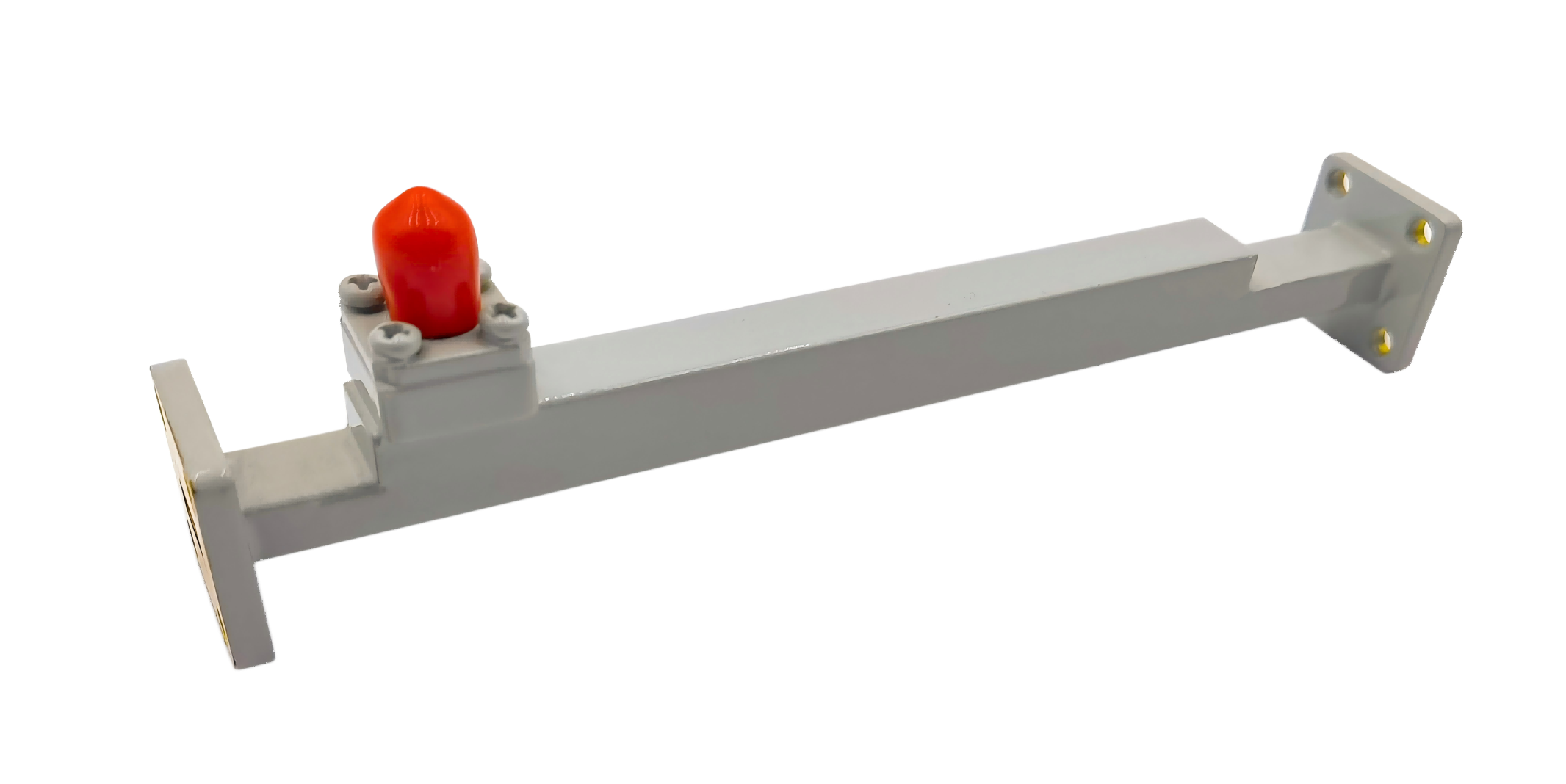
Type 2: Crossguide Directional Couplers (The Space Saver)
When mechanical space is at a premium, engineers turn to the Crossguide Directional Coupler. In this configuration, the secondary waveguide is mounted perpendicularly (at a 90-degree angle) across the broad wall of the main waveguide, forming a cross shape.
This perpendicular design drastically reduces the overall length of the component. When mechanical space is severely restricted inside a UAV payload, a portable radar system, or a dense 5G transceiver, integrating crossguide directional couplers provides the necessary power monitoring in an ultra-compact footprint. While they offer moderate directivity (typically 15 dB to 20 dB), they are highly cost-effective and perfect for basic power monitoring where extreme VSWR precision is not the primary goal.
Type 3: Waveguide Loop Couplers (The Magnetic Sampler)
Sometimes, you don't need a secondary waveguide output; you just need to route the sampled RF signal directly into a standard coaxial power meter or spectrum analyzer. Instead of a secondary waveguide, a Loop Coupler uses a small conductive loop inserted into the main waveguide to sample the magnetic field (H-field).
For high-power industrial microwave heating, broadcast transmitters, or systems requiring a direct connection to coaxial test equipment, utilizing a waveguide loop coupler provides a seamless waveguide-to-coaxial transition. Some advanced designs even allow the loop depth to be adjusted to fine-tune the coupling factor, offering excellent flexibility for high-power, lower-frequency applications.
Type 4: Waveguide Probe Couplers (The Electric Sampler)
Similar to the loop coupler, the Probe Coupler outputs directly to a coaxial connector (such as an SMA or N-Type). However, instead of a loop, it uses a straight metallic probe (antenna) inserted into the waveguide to sample the electric field (E-field).
If your system only requires basic signal injection, frequency monitoring, or extracting a small sample for a spectrum analyzer without strict directivity needs, a waveguide probe coupler offers a simple, highly cost-effective solution. While they are typically non-directional, their compact size and direct coaxial output make them incredibly convenient for general laboratory testing.
Quick Reference Comparison Guide
To help procurement teams and system integrators make quick, informed decisions, here is a side-by-side comparison of the four coupler types:
| Coupler Type | Coupling Mechanism | Directivity (Accuracy) | Output Interface | Primary Use Case |
|---|---|---|---|---|
| Broadwall | Multi-hole array (Parallel) | Very High (>35 dB) | Waveguide | Precision VSWR protection & EMC testing |
| Crossguide | Cross-slot (Perpendicular) | Moderate (15-20 dB) | Waveguide | Space-constrained power monitoring (UAVs) |
| Loop Coupler | Magnetic field (H-field) loop | Low to Moderate | Coaxial (SMA, N-Type) | High-power monitoring with direct coax output |
| Probe Coupler | Electric field (E-field) probe | Poor / Non-directional | Coaxial (SMA, N-Type) | Basic signal sampling & frequency monitoring |
Overcoming Supply Chain Fragility with Agile Manufacturing
Choosing the right type of waveguide coupler is a critical step in designing a robust RF system. However, the true challenge for system integrators today is securing these precision components on time to meet strict project deadlines.
For decades, the RF industry has relied on a handful of legacy Western manufacturers. While their quality is established, their rigid, bureaucratic supply chains often result in agonizing 16 to 24-week lead times. When you are deploying a new satellite earth station or upgrading a critical EMC test bench, waiting half a year for a specific coupler is unacceptable. It stalls projects, frustrates stakeholders, and delays your time-to-market.
We believe that your supplier should be a strategic partner, not a bottleneck. As a true source manufacturer, AO Microwave offers deep customization capabilities across all four types of couplers (Broadwall, Crossguide, Loop, and Probe). Whether you need a specific coupling factor, a unique flange style, or ultra-high-frequency support up to 110 GHz, our engineering team can design and manufacture the exact component you need. Combined with our agile manufacturing process, we deliver these tailored, industrial-grade solutions rapidly, ensuring your project stays on schedule without compromising on signal integrity.
Conclusion: Making the Right Architectural Choice
Understanding the trade-offs between different waveguide couplers ensures that your system operates safely, efficiently, and within budget. If accuracy and precise VSWR monitoring are your top priorities, the Broadwall Coupler is your undisputed champion. If you are fighting for every millimeter of space, the Crossguide Coupler is your best ally. And for seamless coaxial integration, Loop and Probe couplers provide the perfect bridge.
By partnering with a reliable manufacturer of industrial-grade components, you can secure the high performance your engineers demand without the inflated price tags and long lead times that procurement managers dread.
Ready to Specify the Perfect Coupler for Your RF System?
Don't let confusing specifications or rigid supply chains delay your project. Whether you need a high-directivity Broadwall coupler for a Satcom uplink, a compact Crossguide for a drone payload, or a convenient Loop coupler for direct coaxial measurement, AO Microwave has the industrial-grade solutions you need.
Contact our engineering sales team today for a technical consultation or a custom quote, and let us help you build a more reliable, cost-effective RF architecture.