
Confused by Waveguide Sizes and Standards? How to Choose the Right WR Band for Your RF Project?
Confused by WR waveguide sizes? Demystify EIA vs IEC standards, avoid overpaying for aerospace-grade, and choose the right RF components for your next project.
Confused by Waveguide Sizes and Standards? How to Choose the Right WR Band for Your RF Project?
If you are an RF engineer, a procurement manager, or a system integrator working in telecommunications, satellite communications, or defense, you already know the pressure of getting the Bill of Materials (BOM) exactly right. A single mismatched component can lead to severe signal attenuation, delayed project timelines, and skyrocketing costs.
One of the most common hurdles professionals face is navigating the complex world of waveguide sizes and standards. With the global RF and microwave components market projected to surpass $30 billion by 2028—driven heavily by 5G expansion, UAV (drone) technology, and satellite constellations—understanding how to specify the correct waveguide has never been more critical.
Are you struggling to translate EIA (WR) standards to IEC (R) standards? Are you worried about overpaying for "aerospace-grade" components when high-quality industrial-grade parts would perfectly suit your telecom or EMC testing needs?
In this comprehensive guide, we will demystify common waveguide sizes, explain the critical standards, and help you make cost-effective, technically sound decisions for your next RF project.
Why Does Waveguide Size Matter So Much in RF Systems?
Unlike coaxial cables, which use a center conductor to transmit signals, a waveguide is essentially a hollow metallic pipe that confines and directs electromagnetic waves. The physical dimensions of this "pipe" dictate exactly which frequencies can pass through it.
This brings us to the most critical concept in waveguide selection: the Cutoff Frequency.
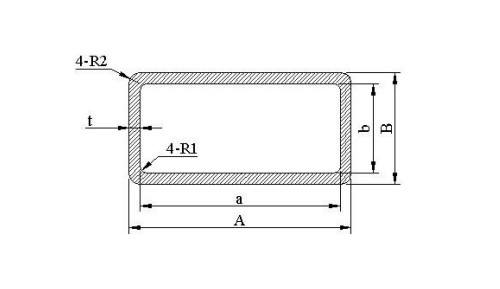
Every rectangular waveguide acts as a high-pass filter. The broad wall dimension (usually denoted as 'a') determines the lowest frequency that can propagate through the waveguide. If you attempt to push a signal below this cutoff frequency, the wave will rapidly attenuate and fail to transmit. Conversely, if the frequency is too high for the specific waveguide size, higher-order modes will generate, causing signal distortion and interference.
Decoding the Alphabet Soup: EIA (WR) vs. IEC (R) Standards
When sourcing RF microwave components globally, you will encounter two primary naming conventions. Understanding both is essential for seamless international procurement.
1. The EIA Standard (WR Designations)
Predominantly used in North America and widely accepted globally, the Electronic Industries Alliance (EIA) uses the "WR" prefix, which stands for Waveguide Rectangular. The number that follows represents the inner width (the broad wall 'a') of the waveguide in hundredths of an inch.
Example: A WR-90 waveguide has an inner width of 0.90 inches. A WR-28 has an inner width of 0.28 inches.
2. The IEC Standard (R Designations)
The International Electrotechnical Commission (IEC) standard is frequently used in Europe and other parts of the world. It uses the prefix "R" followed by a number. Unlike the WR system, this number does not represent a physical dimension; instead, it roughly corresponds to the recommended frequency range in hundreds of Megahertz (MHz).
Example: A WR-90 waveguide is equivalent to an R100 in the IEC standard.
Standard Waveguide Sizes and Frequency Chart
To save you hours of cross-referencing, we have compiled a quick-reference chart of the most common waveguide sizes used in industrial, telecom, and defense applications today.
| EIA Standard (USA) | IEC Standard (Europe) | Band Designation | Frequency Range (GHz) | Common Applications |
|---|---|---|---|---|
| WR-284 | R32 | S-Band | 2.60 - 3.95 | Air traffic control, weather radar, medical linear accelerators. |
| WR-137 | R70 | C-Band | 5.85 - 8.20 | Satellite communications, telecommunications, marine radar. |
| WR-90 | R100 | X-Band | 8.20 - 12.40 | Military radar, EMC testing, industrial microwave heating. |
| WR-75 | R120 | Ku-Band | 10.00 - 15.00 | VSAT, satellite broadcasting, UAV data links. |
| WR-42 | R220 | K-Band | 18.00 - 26.50 | Automotive radar, high-resolution mapping, astronomy. |
| WR-28 | R320 | Ka-Band | 26.50 - 40.00 | 5G backhaul, high-throughput satellites, defense systems. |
The Hidden Trap: Are You Overpaying for "Aerospace-Grade"?
One of the biggest budget-killers in RF procurement is over-specifying. Many engineers and buyers fall into the trap of believing that only ultra-expensive, high-precision aerospace-grade components will guarantee system reliability.
The truth? Unless your component is literally being launched into deep space on a multi-billion-dollar satellite, you likely do not need aerospace-grade pricing.
For applications like 5G base stations, commercial UAVs, EMC testing chambers, medical equipment, and terrestrial satellite communications, high-quality industrial-grade components offer the perfect balance. They provide excellent VSWR (Voltage Standing Wave Ratio), low insertion loss, and robust durability, but at a fraction of the cost and with significantly shorter lead times.
This is where AO Microwave steps in. We specialize in manufacturing premium industrial-grade waveguides, antennas, and RF coaxial components. By focusing on the exact tolerances required for commercial and industrial applications, we help our clients slash their BOM costs without sacrificing a single decibel of performance.
3 Critical Factors to Consider Before Ordering Waveguide Components
Choosing the right WR size is only the first step. To ensure your system integrates flawlessly, you must also consider the following:
1. Material Selection: Aluminum vs. Copper/Brass
Waveguides are typically manufactured from Aluminum (like 6061-T6) or Copper/Brass alloys.
- Aluminum: Lightweight and cost-effective. It is the go-to choice for aviation, UAVs, and large telecom installations where weight is a primary concern.
- Copper/Brass: Offers slightly better electrical conductivity and lower insertion loss. It is ideal for high-power applications, EMC testing, and medical devices where weight is less of an issue.
2. Flange Types: The Connection Matters
A waveguide is useless if it cannot connect to your existing system. Flange mismatches are a massive headache for system integrators. You must specify whether you need a Cover flange (flat), a Choke flange (grooved to prevent RF leakage), or specific styles like CPRG (Contact Pressurizable Rectangular Grooved) or CPRF (Flat). Always double-check your mating components before ordering.
3. Surface Treatment and Plating
For industrial applications exposed to the elements (like 5G towers or marine radar), corrosion resistance is vital. Ensure your supplier offers appropriate surface treatments, such as chromate conversion coating (Iridite/Alodine) for aluminum, or silver plating for brass to enhance conductivity and reduce skin effect losses at higher frequencies.
How to Avoid Supply Chain Headaches in Your Next RF Project
In today's volatile global market, finding a supplier who can deliver on time is just as important as the technical specifications. Long lead times from traditional Western manufacturers can stall your projects for months.
To mitigate this risk, partner with a manufacturer that controls its own machining and assembly processes. At AO Microwave, we understand the fast-paced demands of the European and American markets. Whether you need standard WR-90 waveguide sections, custom coaxial cable assemblies, or specialized horn antennas, we provide rapid prototyping, transparent communication, and reliable mass production tailored to your exact industrial requirements.
Ready to Optimize Your RF System and Reduce Costs?
Stop letting confusing standards and overpriced components delay your projects. Our team of experienced RF specialists is ready to help you select the perfect waveguide sizes, flanges, and materials for your specific application.
Contact us today for a technical consultation or a custom quote, and let's build a more efficient, cost-effective RF system together.