
Overwhelmed by Specs? How to Choose the Right Waveguide Coupler (Broadwall, Crossguide, Loop, or Probe) for Your RF System?
How to choose the right waveguide coupler? Compare Broadwall, Crossguide, Loop, and Probe couplers. Learn to calculate coupling factors and reduce BOM costs.
Overwhelmed by Specs? How to Choose the Right Waveguide Coupler (Broadwall, Crossguide, Loop, or Probe) for Your RF System?
Designing a high-power RF system is a high-stakes balancing act. Whether you are an engineer integrating a new 5G mmWave backhaul, or a procurement manager sourcing components for a commercial satellite earth station, you know that a single mismatched component can jeopardize the entire project.
When it comes to monitoring RF power and protecting your expensive High-Power Amplifiers (HPAs) from catastrophic reflected energy, the waveguide coupler is your first line of defense. But with the global RF and microwave components market projected to surpass $30 billion by 2028, the sheer variety of couplers available on the market is staggering.
Should you specify a Broadwall, a Crossguide, a Loop, or a Probe coupler? How do you know which coupling factor is safe for your power meter? And most importantly, how do you avoid blowing your budget on overpriced "aerospace-grade" components when industrial-grade parts would perform flawlessly?
If you are asking yourself, "How to choose the right waveguide coupler for your RF system?", you are in the right place. In this comprehensive, step-by-step guide, we will demystify the critical specifications, compare the four main types of couplers, and show you how to optimize your Bill of Materials (BOM) without sacrificing a single decibel of reliability.
Step 1: Determine Your Frequency Band and Waveguide Size (WR)
The very first step in selecting a waveguide coupler is matching it to your system's operating frequency. Unlike coaxial cables, waveguides act as high-pass filters. Their physical dimensions dictate which frequencies can propagate through them.
You must select the correct Electronic Industries Alliance (EIA) standard size, denoted by the "WR" (Waveguide Rectangular) prefix. For example:
- C-Band (5.85 - 8.20 GHz): Requires WR-137. Common in marine radar and legacy satellite communications.
- X-Band (8.20 - 12.40 GHz): Requires WR-90. The standard for defense radar and EMC testing.
- Ku-Band (10.0 - 15.0 GHz): Requires WR-75. Widely used in VSAT and UAV data links.
- Ka-Band (26.5 - 40.0 GHz): Requires WR-28. Essential for high-throughput satellites and 5G networks.
Step 2: Calculate the Required Coupling Factor (dB)
The Coupling Factor tells you exactly how much of the main RF signal is "siphoned off" to the coupled port for measurement. It is expressed in decibels (dB). Choosing the wrong coupling factor can either fry your sensitive test equipment or provide a signal too weak to measure.
To choose the right factor, you need to know your system's peak input power and the maximum safe input power of your measuring device (like a spectrum analyzer or power meter).
The Quick Math:
Let's say your transmitter outputs 10,000 Watts (10 kW) of peak power. Your power meter can only safely handle 1 Watt.
- A 30 dB Coupler reduces the power by a factor of 1,000. (10,000W / 1,000 = 10 Watts). Result: Your power meter burns out.
- A 40 dB Coupler reduces the power by a factor of 10,000. (10,000W / 10,000 = 1 Watt). Result: Perfect safe measurement.
- A 50 dB Coupler reduces the power by a factor of 100,000. (10,000W / 100,000 = 0.1 Watts). Result: Safe, but might be too close to the noise floor depending on your equipment.
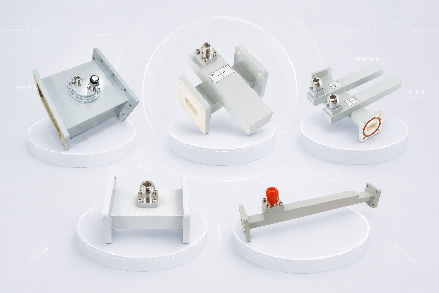
Step 3: Understand the 4 Main Types of Waveguide Couplers
Once you have your electrical specs, you must choose the physical coupling mechanism. This is where many engineers get stuck. The choice depends entirely on your need for accuracy (Directivity), mechanical space, and how you plan to connect your test equipment.
1. Broadwall Directional Coupler (The Precision King)
In this design, the secondary waveguide is attached parallel to the broad wall of the main waveguide, sharing a common wall with multiple precisely machined holes spaced at quarter-wavelength intervals.
- Pros: Exceptional directivity (>35 dB to 40+ dB) and broad bandwidth. It is the gold standard for highly accurate VSWR monitoring.
- Cons: Physically long, bulky, and more expensive to manufacture.
- Best For: EMC testing chambers, medical LINACs, and satellite earth stations where precision is critical and space is available.
2. Crossguide Directional Coupler (The Space Saver)
The secondary waveguide is mounted perpendicularly (at a 90-degree angle) across the broad wall of the main waveguide, forming a cross shape.
- Pros: Ultra-compact footprint and cost-effective.
- Cons: Moderate directivity (typically 15-20 dB) and narrower bandwidth compared to broadwall designs.
- Best For: UAV payloads, portable radar, and compact 5G base stations where mechanical space is strictly limited.
3. Waveguide Loop Coupler (The Magnetic Sampler)
Instead of a secondary waveguide, a Loop Coupler uses a small conductive loop inserted into the main waveguide to sample the magnetic field (H-field). The sampled signal is usually routed directly to a coaxial connector (like SMA or N-Type) mounted on the outside of the waveguide.
- Pros: Provides a direct Waveguide-to-Coaxial transition, eliminating the need for extra adapters. Excellent for high-power, lower-frequency applications. Some designs allow the loop depth to be adjusted to fine-tune the coupling factor.
- Cons: Directivity is generally lower than broadwall couplers, and it can be sensitive to frequency variations.
- Best For: High-power industrial microwave heating, broadcast transmitters, and systems requiring direct connection to coaxial power meters.
4. Waveguide Probe Coupler (The Electric Sampler)
Similar to the loop coupler, but instead of a loop, it uses a straight metallic probe (antenna) inserted into the waveguide to sample the electric field (E-field). It also outputs directly to a coaxial connector.
- Pros: Very simple, compact, and cost-effective. Great for basic signal injection or extracting a small sample for a spectrum analyzer.
- Cons: Typically non-directional (or has very poor directivity). It cannot accurately distinguish between forward and reflected power.
- Best For: Basic signal sampling, frequency monitoring, or injecting a local oscillator (LO) signal where VSWR protection is not the primary goal.
Step 4: Quick Reference Comparison Guide
To help procurement teams and system integrators make quick decisions, here is a side-by-side comparison of the four coupler types:
| Coupler Type | Coupling Mechanism | Directivity (Accuracy) | Output Interface | Primary Use Case |
|---|---|---|---|---|
| Broadwall | Multi-hole array (Parallel) | Very High (>35 dB) | Waveguide | Precision VSWR protection & EMC testing |
| Crossguide | Cross-slot (Perpendicular) | Moderate (15-20 dB) | Waveguide | Space-constrained power monitoring (UAVs) |
| Loop Coupler | Magnetic field (H-field) loop | Low to Moderate | Coaxial (SMA, N-Type) | High-power monitoring with direct coax output |
| Probe Coupler | Electric field (E-field) probe | Poor / Non-directional | Coaxial (SMA, N-Type) | Basic signal sampling & frequency monitoring |
Step 5: The "Aerospace-Grade" Trap (How to Optimize Your BOM)
Once engineers finalize the specs, procurement managers face the ultimate hurdle: the budget. There is a pervasive myth in the RF industry that to get a reliable coupler, you must buy ultra-expensive "aerospace-grade" components from legacy Western brands, often enduring 16 to 20-week lead times.
This is a massive drain on your project budget and timeline.
Unless your system is literally being launched into deep space, you do not need to pay the premium for aerospace-grade certification. For terrestrial applications—such as 5G telecom networks, commercial satellite earth stations, EMC testing labs, and defense radar—high-quality industrial-grade waveguide couplers offer the exact same electrical performance at a fraction of the cost.
Step 6: Don't Forget the Flanges and Materials
The final step is ensuring your coupler can physically connect to your existing system. A brilliant coupler is useless if the flanges don't match, leading to RF leakage and impedance mismatches.
- Material: Choose Aluminum for lightweight applications (like UAVs or aviation). Choose Copper or Brass for maximum thermal dissipation in high-power continuous wave (CW) applications (like EMC testing or medical equipment).
- Flange Type: Double-check your mating components. Do you need a flat Cover flange, a grooved Choke flange (to prevent RF leakage), or a specific CPRG/CPRF style? Always specify this clearly when requesting a quote.
Conclusion: Make the Smart Choice for Your RF Architecture
Choosing the right waveguide coupler doesn't have to be a guessing game. By systematically evaluating your frequency band, calculating the correct coupling factor, and understanding the distinct advantages of Broadwall, Crossguide, Loop, and Probe designs, you can ensure your RF system operates safely and efficiently.
More importantly, by breaking free from the "aerospace-grade" myth and partnering with a reliable manufacturer of industrial-grade components, you can achieve world-class RF performance while keeping your supply chain agile and your budget intact.
Ready to Specify the Perfect Coupler for Your Project?
Don't let confusing specifications or overpriced components delay your system integration. Whether you need a high-directivity Broadwall coupler for a Satcom uplink, a compact Crossguide for a drone, or a convenient Loop coupler for direct coaxial measurement, AO Microwave has the industrial-grade solutions you need.
Contact our engineering sales team today for a technical consultation or a custom quote, and let us help you build a more reliable, cost-effective RF architecture.