
Securing Mission-Critical Uptime: Waveguide Switches Explained, Types, and RF Applications
Secure mission-critical uptime with precision waveguide switches. Learn how SPDT and DPDT transfer switches ensure RF redundancy and signal integrity.
Securing Mission-Critical Uptime: Waveguide Switches Explained, Types, and RF Applications
In the high-stakes arenas of satellite communications, 5G telecommunications, and defense radar, system downtime is not an option. When a High-Power Amplifier (HPA) fails in a commercial satellite earth station, or when a radar system loses its primary transmission path, the consequences extend far beyond hardware replacement. It means lost data, compromised security, and severe damage to a network's reputation.
To guarantee continuous operation, engineers design sophisticated redundancy architectures. The beating heart of these fail-safe systems is a highly precise electromechanical device: the Waveguide Switch.
By automatically routing RF signals from a failed primary component to a standby backup in a matter of milliseconds, waveguide switches ensure that your network remains online, no matter what happens behind the scenes. However, specifying the wrong type of switch—or underestimating the mechanical precision required for high-power routing—can introduce severe insertion loss, crosstalk, or even catastrophic internal arcing.
In this comprehensive guide, we will explore the mechanics of waveguide switches, decode the critical differences between SPDT and DPDT configurations, and demonstrate how partnering with an agile, industrial-grade manufacturer can fortify your RF architecture and streamline your project timelines.
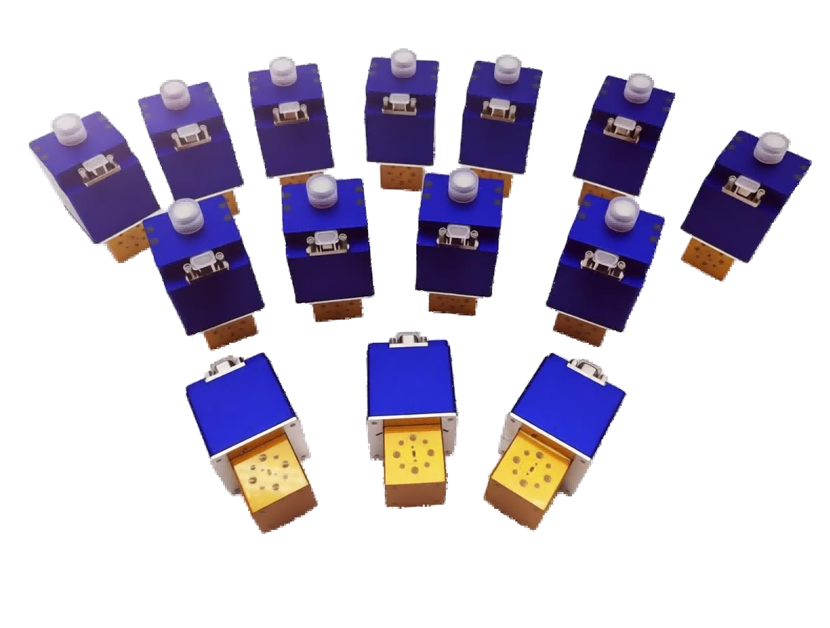
The Mechanics of Reliability: How Does a Waveguide Switch Work?
Unlike solid-state switches (which use PIN diodes and are typically limited to lower-power coaxial applications), a waveguide switch is a robust electromechanical device. It is designed to physically alter the path of an electromagnetic wave traveling through a waveguide system without degrading the signal.
Inside the switch housing (the stator), there is a precisely CNC-machined rotating cylinder (the rotor) containing curved waveguide channels. When a command is sent to the switch's electronic drive motor, the rotor turns—usually by 90 degrees. This movement physically disconnects the RF signal from one output port and seamlessly aligns the internal channel with a different output port.
Because they use physical waveguide channels rather than semiconductor junctions, electromechanical waveguide switches offer ultra-low insertion loss and massive power handling capabilities, making them indispensable for microwave and millimeter-wave frequencies (X, Ku, K, and Ka bands).
One of the most critical operational protocols in RF redundancy is avoiding "Hot Switching." This occurs when a switch is activated while high-power RF energy is still flowing through it. As the rotor turns, the physical gap creates a massive impedance mismatch, causing the RF energy to arc (spark) across the contacts, instantly degrading the internal channels. Always implement "Cold Switching"—ensure your system logic mutes the RF amplifier for the 50 to 100 milliseconds it takes for the switch rotor to lock securely into its new position.
Decoding the Types of Waveguide Switches
When designing a signal routing matrix or a redundancy system, engineers primarily choose between two mechanical configurations. Selecting the right one dictates how your system handles backups, testing, and signal distribution.
1. SPDT (Single Pole Double Throw)
The SPDT switch has one input port and two output ports (or vice versa). It acts as a highly efficient diverter. The signal enters the common port and is routed to either Port A or Port B.
- Antenna Routing: Routing a single high-power transmitter to either a primary directional horn antenna or a secondary omnidirectional antenna based on operational needs.
- Automated Testing: In EMC laboratories, SPDT switches are used to route a signal from a single generator to multiple Devices Under Test (DUTs), fully automating the testing process without manual cable swapping.
2. DPDT / Transfer Switch (Double Pole Double Throw)
Often referred to as a Transfer Switch, this is the undisputed king of RF redundancy. It features four ports. In its default state, Port 1 connects to Port 2, and Port 3 connects to Port 4. When switched, the internal rotor turns, connecting Port 1 to Port 4, and Port 3 to Port 2.
- 1:1 Redundancy Systems: In a satellite uplink, you have a Main Amplifier and a Standby Amplifier. The Transfer Switch routes the input signal to the Main Amplifier, while simultaneously routing the Standby Amplifier to a dummy load (for safe testing and warm-up). If the Main Amplifier fails, the switch flips. The input is instantly routed to the Standby Amplifier, keeping the network online, while the failed Main Amplifier is routed to the dummy load for safe removal and repair.
4 Critical Specifications for Uncompromising Signal Integrity
When system integrators are sourcing waveguide switches, evaluating these four specifications is critical to ensuring long-term reliability and pristine signal integrity:
1. Isolation (Crosstalk Prevention)
Isolation measures how well the switch prevents the RF signal from leaking into the disconnected port. In high-power systems, poor isolation is disastrous. If you are transmitting 1,000 Watts and the switch has poor isolation, enough power could leak into the standby receiver to destroy it. Premium industrial-grade switches must offer >60 dB to 80 dB of isolation.
2. Insertion Loss
Every fraction of a decibel matters. Because the signal must pass through the rotating internal channels, a poorly machined rotor will introduce resistance. High-quality waveguide switches maintain an insertion loss of < 0.1 dB, ensuring your amplifier's power reaches the antenna without generating excess heat.
3. Switching Time
This is the time it takes for the motor to turn the rotor and lock it into the new position. In telecommunications, faster is better to minimize data packet loss during a redundancy switchover. Standard industrial waveguide switches typically operate in the 50 ms to 100 ms range, providing rapid, reliable transitions.
4. Mechanical Lifespan (MTBF)
Because waveguide switches rely on moving mechanical parts (motors, bearings, and rotors), durability is paramount. A premium switch should guarantee a minimum lifespan of 100,000 to 250,000 actuations. For applications requiring constant, rapid switching (like automated production line testing), mechanical longevity is your most critical metric.
Overcoming Supply Chain Bottlenecks with Agile Manufacturing
In today's fast-paced technology landscape, designing a brilliant RF architecture is only half the battle. The other half is actually getting the components on time.
For decades, the RF industry has been dominated by legacy Western manufacturers. While their quality is recognized, their rigid supply chains often result in agonizing 16 to 24-week lead times. When you are building a new 5G infrastructure or upgrading a satellite earth station, waiting half a year for a critical transfer switch can derail your entire project timeline.
System integrators need more than just a component; they need a responsive, agile partner.
Conclusion: Automate Your Reliability
In modern microwave systems, hoping your equipment never fails is not a strategy. A well-engineered redundancy architecture, powered by high-precision waveguide switches, is the only way to guarantee continuous uptime and protect your network's integrity.
By understanding the mechanical differences between SPDT and Transfer switches, strictly enforcing "Cold Switching" protocols, and prioritizing isolation and insertion loss, you can build a bulletproof RF network. Furthermore, by partnering with an agile manufacturer dedicated to industrial-grade excellence, you can ensure your projects are delivered on time, every time.
Ready to Fortify Your RF Redundancy System?
Don't let component failures cause network outages, and don't let rigid supply chains delay your project launches. Whether you need a precision SPDT switch for an EMC automated test bench or a robust DPDT Transfer Switch for a Satcom 1:1 redundancy matrix, AO Microwave delivers the reliability and responsiveness you need.
Contact our engineering team today for a technical consultation, and let us help you build a resilient, high-performance RF architecture.