
Stop Over-Engineering: The Smart Guide to Sizing and Selecting Waveguide Loads for RF Systems
Stop over-engineering your RF system. Learn how to size waveguide loads by balancing thermal derating, material weight, and VSWR for smart, cost-effective design.
Stop Over-Engineering: The Smart Guide to Sizing and Selecting Waveguide Loads for RF Systems
When designing a microwave architecture, selecting a waveguide load seems like a straightforward task. You check the frequency band, look at the power rating, and order the part. However, this oversimplified approach often leads to one of two costly extremes: under-specifying, which results in thermal failure, or over-engineering, which needlessly inflates your Bill of Materials (BOM) and consumes valuable mechanical space.
In reality, choosing the right waveguide load is a complex exercise in balancing trade-offs. It requires a deep understanding of your system's operating environment, thermal dynamics, and the actual precision required for your specific application.
Do you really need a massive, liquid-cooled dummy load, or would a strategically placed finned aluminum load suffice? Does your system operate at high altitudes where air density affects cooling? Are you paying a premium for an ultra-low VSWR of 1.03 when 1.15 would perfectly meet your system's needs?
In this advanced selection guide, we will move beyond the basic specifications. We will explore the critical engineering trade-offs involved in sizing waveguide loads, helping system integrators and procurement managers make smarter, more cost-effective decisions without compromising on industrial-grade reliability.
Trade-off 1: Material Selection (Weight vs. Thermal Conductivity)
Because a waveguide load converts 100% of absorbed RF energy into heat, the material of the housing is critical. Engineers must balance the need for thermal dissipation against the strict weight limits of their mechanical enclosures.
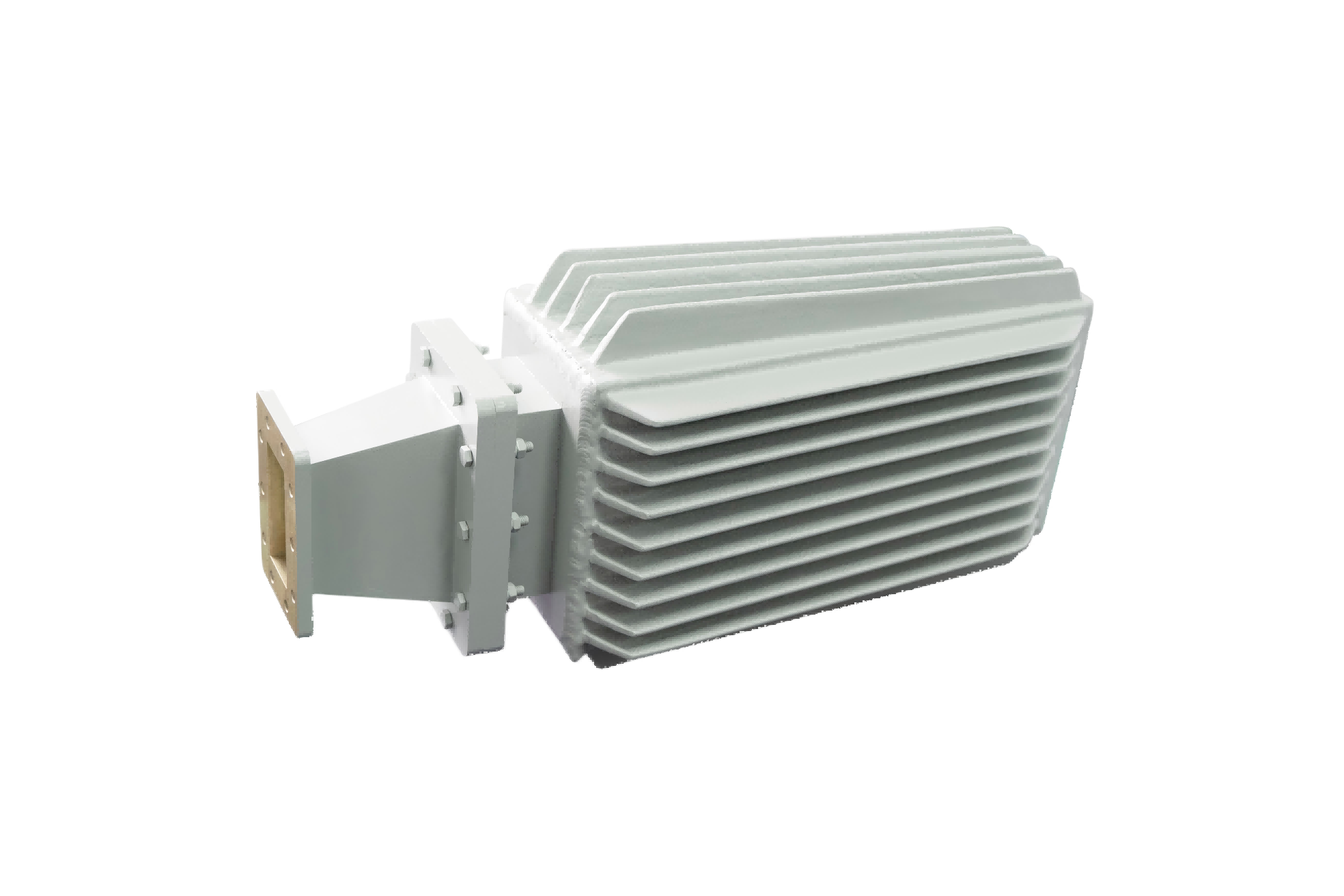
- Aluminum (The Lightweight Champion): Aluminum is the industry standard for a reason. It is lightweight, cost-effective, and offers good thermal conductivity. If you are designing a payload for a UAV, an aviation radar system, or a mast-mounted 5G transceiver, aluminum is your go-to material to keep the overall system weight down.
- Copper and Brass (The Thermal Heavyweights): Copper has nearly double the thermal conductivity of aluminum. If your application involves extreme Continuous Wave (CW) power in a confined space—such as a medical linear accelerator (LINAC) or a ground-based EMC testing chamber—copper or brass loads will pull heat away from the internal absorptive element much faster. The trade-off? They are significantly heavier and more expensive.
Trade-off 2: Environmental Realities and Thermal Derating
A common mistake is selecting a load based purely on its datasheet power rating, which is typically calculated at a standard room temperature (e.g., 25°C / 77°F) at sea level. But RF systems rarely operate in perfect laboratory conditions.
When selecting a high-power dummy load, you must account for Thermal Derating based on your actual operating environment:
If your satellite earth station is located in a high-altitude desert, you face two problems. First, high ambient temperatures (e.g., 50°C) mean the load cannot dissipate heat as efficiently. Second, at high altitudes, the air is thinner. Less dense air means natural convection cooling is severely degraded, and the dielectric strength of the air inside the waveguide drops, increasing the risk of high-power arcing. In these environments, a load rated for 500W at sea level might only safely handle 300W. You must either over-size the load or specify forced-air cooling.
Trade-off 3: The VSWR Sweet Spot (Precision vs. Budget)
Voltage Standing Wave Ratio (VSWR) measures how much signal reflects off the load. While every engineer wants a perfect 1.0:1 match, achieving ultra-low VSWR requires extensive CNC machining time and meticulous manual tuning of the absorptive element, which drives up the cost.
Smart specifying means knowing exactly how much precision your application actually requires:
| Application Scenario | Recommended VSWR | Why? |
|---|---|---|
| VNA Calibration & Metrology | < 1.03:1 | In a laboratory, the load acts as the absolute reference standard. Any reflection here will permanently skew all subsequent measurements. You must pay for maximum precision. |
| Satcom 1:1 Redundancy Isolation | < 1.10:1 | When terminating a standby amplifier, you need excellent absorption to prevent leakage into the active transmission path, but laboratory-grade perfection is not strictly necessary. |
| General Transmitter Dummy Loads | < 1.15:1 to 1.20:1 | When running a radar transmitter into a dummy load for offline maintenance, the goal is safe heat dissipation. A VSWR of 1.15 is more than sufficient to protect the magnetron while keeping component costs reasonable. |
Trade-off 4: Form Factor and Customization
Standard catalog loads are designed for general use, but modern RF enclosures are becoming increasingly dense. Trying to force a standard, bulky finned load into a compact transceiver chassis often leads to mechanical interference or poor airflow, which ultimately causes the load to overheat.
Instead of redesigning your entire chassis to fit a standard component, the smarter approach is to customize the component to fit your chassis.
At AO Microwave, we understand that true industrial-grade reliability requires components that fit your exact mechanical and thermal footprint. Because we control the entire manufacturing process, we offer deep customization capabilities. Need the cooling fins oriented horizontally instead of vertically to match your system's airflow? Need a specific mounting bracket integrated into the housing? Need a WR-10 load optimized for 110 GHz? Our engineering team can design and deliver tailored solutions rapidly, ensuring your system is optimized for both performance and space.
Conclusion: Specify with Intelligence
Choosing the right waveguide load is not about blindly picking the highest specs from a catalog; it is about intelligent engineering. By carefully weighing the trade-offs between material weight and thermal conductivity, accounting for environmental derating, and targeting the exact VSWR your application demands, you can optimize your system's performance while keeping your budget under control.
By partnering with an agile, source manufacturer like AO Microwave, you gain the flexibility to customize your components to your exact architectural needs, breaking free from the constraints and long lead times of legacy suppliers.
Ready to Optimize Your RF Architecture?
Stop over-engineering and start smart-specifying. Whether you need ultra-precision loads for VNA calibration, lightweight aluminum loads for UAVs, or custom-finned dummy loads for high-altitude deployments, AO Microwave has the engineering expertise to deliver exactly what you need.
Contact our engineering team today to discuss your specific environmental and mechanical requirements, and let us design the perfect tailored solution for your system.