
How to Choose the Right Waveguide Switch?
Waveguide switches are critical components in many high-frequency systems, especially in radar, satellite communications, electronic warfare, and millimeter-wave testing. They enable precise signal routing, redundancy switching, and multi-path configuration. However, selecting the right switch is not always straightforward — especially when frequencies reach Ka-band, V-band, W-band, or higher.
At AO Microwave, we provide a complete family of waveguide switches from 5.85 GHz to 110 GHz, covering WR137 to WR10 waveguide bands. To help engineers make the best choice, this guide outlines the key factors to consider when choosing a waveguide switch for your system.
1. Determine the Required Waveguide Band
The first step in selecting a waveguide switch is identifying the waveguide size that matches your operating frequency.
Common millimeter-wave bands include:
-
WR22 (33–50 GHz)
-
WR19 (40–60 GHz)
-
WR15 (50–75 GHz)
-
WR12 (60–90 GHz)
-
WR10 (75–110 GHz)
Each size offers different physical dimensions, insertion loss characteristics, and power-handling capability.
AO Microwave offers precision-machined switches for all these key bands.
2. Choose the Appropriate Switching Configuration
The most common configurations include:
-
SPDT (Single-Pole Double-Throw)
-
DPDT (Double-Pole Double-Throw)
-
Multi-throw switches (custom)
SPDT models are used for simple path selection, while DPDT or multi-throw models support complex routing and redundancy architectures.
AO Microwave provides standard and customized configurations, allowing engineers to match their system topology.
3. Evaluate Insertion Loss and Isolation
Insertion Loss
Important for maintaining signal strength, especially at millimeter-wave frequencies. Lower is always better.
Isolation
Critical for ensuring signals do not leak into unintended paths.
High isolation is essential in:
-
radar receivers
-
EW systems
-
sensitive measurement setups
All AO Microwave waveguide switches are optimized for low insertion loss and high isolation across 5.85–110 GHz.
4. Select the Actuation Method
Waveguide switches can be actuated in different ways:
Electromechanical
-
Most stable and widely used
-
Available in failsafe or latching types
-
Suitable for automated systems
Manual
-
Cost-effective
-
Ideal for labs or low-duty switching environments
AO Microwave provides electromechanical, latching, failsafe, and manual switch options for all waveguide sizes.
5. Check Power Handling Requirements
Power capabilities vary significantly depending on:
-
waveguide band
-
internal switch design
-
material structure
For radar and high-power test systems, ensure the switch supports the peak and average power levels.
AO Microwave designs waveguide switches with robust structures and precise alignment to ensure high power handling and long operation life.
6. Consider Environmental and Mechanical Requirements
Depending on the application, waveguide switches may need to satisfy requirements such as:
-
vibration resistance
-
temperature stability
-
high-cycle lifetime
-
shock durability
-
vacuum or outdoor environments
AO Microwave offers ruggedized models and custom mechanical designs for aerospace, defense, and field-deployed systems.
7. Confirm Connector Compatibility and Mounting
Pay attention to:
-
waveguide flange type
-
mounting holes and orientation
-
interface compatibility with existing equipment
AO Microwave follows industry-standard flange types (UG, UBR, CPR, etc.) and can customize layouts for special installation requirements.
8. Look for Quality, Stability & Supplier Reliability
A waveguide switch is a long-life component expected to function with:
-
stable performance
-
low drift
-
long mechanical lifetime
Choosing a reliable manufacturer ensures better consistency and shorter lead time.
AO Microwave is trusted globally for manufacturing high-precision RF, microwave, and millimeter-wave components with strict quality control and repeatable performance.
Conclusion
Selecting the right waveguide switch requires careful consideration of frequency band, configuration, isolation, actuation method, power capability, and mechanical requirements. By understanding these factors, engineers can build systems that are both highly reliable and optimized for performance.
With a complete lineup ranging from 5.85 GHz to 110 GHz, AO Microwave provides high-performance waveguide switches designed for radar, satellite communications, mmWave testing, and defense applications.
Whether you need WR22, WR19, WR15, WR12, WR10, or custom waveguide switch solutions — AO Microwave has you covered.
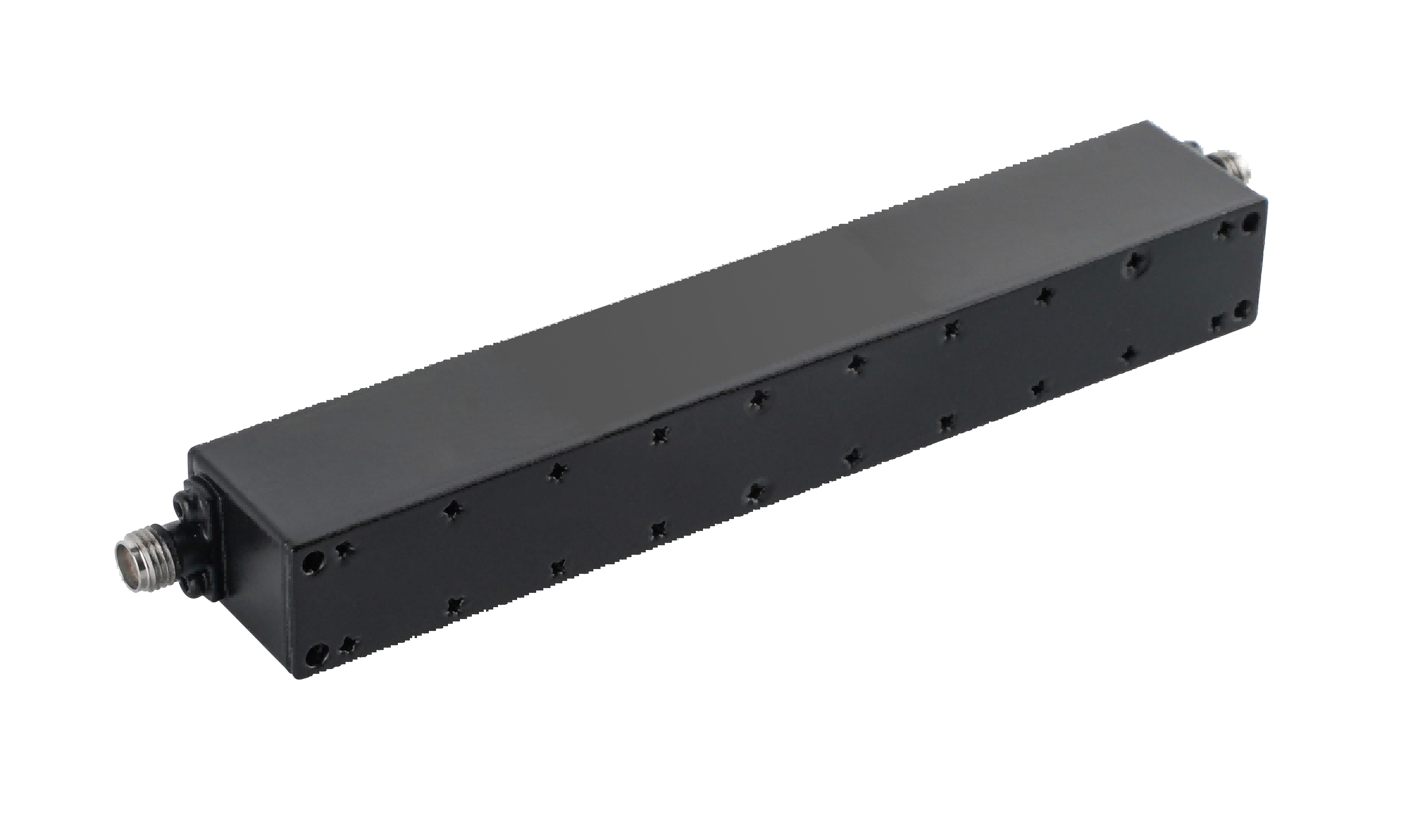 What Types of Coaxial Suspension Line Filters Are Available for RF and Microwave Systems?
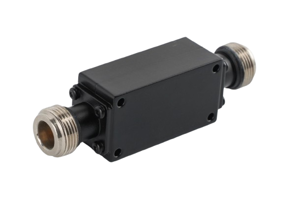 Why Are Coaxial Suspension Line Filters the Right Choice for High-Performance RF Systems?
 What's the Coaxial Suspension Line Filter?
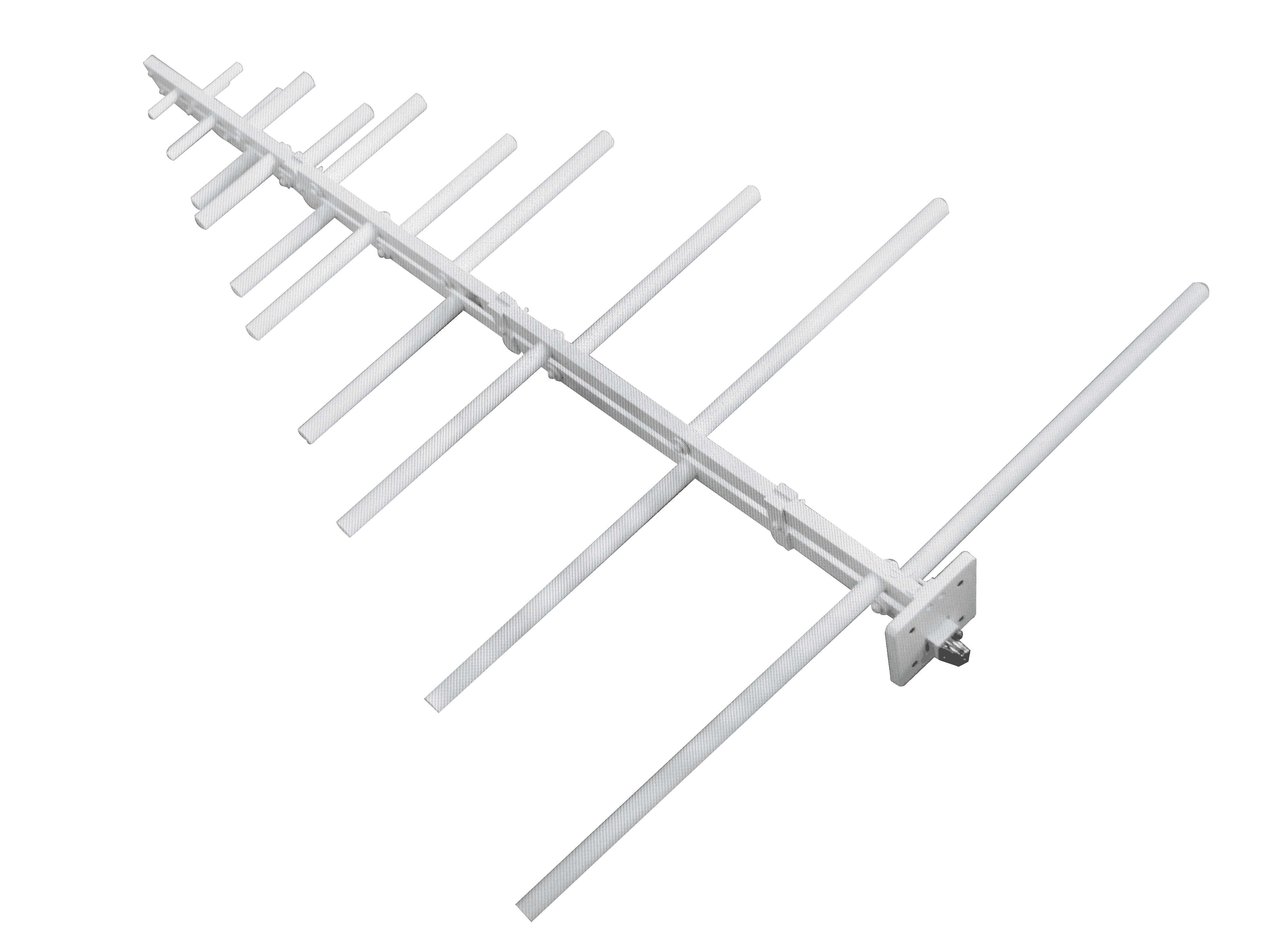 How to Choose a Log-Periodic Antenna for Long-Range Communication?