
How to Choose the Right Waveguide Load for Your Microwave System?
Waveguide loads—also known as waveguide terminations—are essential components in RF and microwave systems. Their main purpose is to absorb microwave energy and prevent reflections that could damage equipment, distort measurements, or degrade system performance.
Selecting the right waveguide load ensures stable operation in radar, satellite communications, EMC testing, millimeter-wave sensing, and laboratory measurements.
Choosing an incorrect load can lead to overheating, high return loss, or even system failure. Below are the key factors engineers should consider, based on industry best practices and the engineering experience of AO Microwave, a trusted manufacturer of high-performance waveguide components.
1. Identify Your Operating Frequency and Waveguide Band
The most fundamental step is matching the waveguide load to your waveguide size.
Common bands include:
-
WR90 (X-band)
-
WR62 (C-band)
-
WR42 (K-band)
-
WR22 (K-band / mmWave)
-
WR19, WR15, WR12, WR10 (millimeter-wave)
Each size supports specific frequency ranges, power levels, and flange types.
AO Microwave offers precision loads covering 0.32 GHz to 110 GHz, ensuring excellent VSWR, stable performance, and tight dimensional tolerances across all standard WR bands.
2. Determine Your Power Handling Requirements
Waveguide loads come in various power ratings:
• Low Power (0.5–5 W)
Used for laboratory measurements, test setups, and system terminations.
• Medium Power (5–50 W)
Suitable for communication systems, radar subsystems, and general RF loads.
• High Power (50–500+ W)
Used in transmitters, EMC systems, and high-power radar applications.
Selecting a load with insufficient power rating can lead to:
-
overheating
-
permanent damage
-
change in RF characteristics
-
safety hazards
AO Microwave designs waveguide loads with superior heat-dissipation structures and high-stability resistive materials, ensuring long-term reliability even under continuous high-power operation.
3. Evaluate Return Loss / VSWR Performance
The effectiveness of a waveguide load is measured by how well it absorbs RF energy.
Look for:
-
Low VSWR (1.03–1.25 at most frequencies)
-
High return loss (20–30 dB or better)
Poor VSWR leads to:
-
reflected power
-
inaccurate measurements
-
interference in sensitive receivers
AO Microwave uses precision machining and advanced absorbing materials to achieve consistently low VSWR across the entire waveguide band.
4. Select the Right Type: Fixed Load or Sliding Load
Fixed Loads
-
Standard design
-
Used for permanent terminations
-
Compact and cost-effective
Sliding / Variable Loads
-
Used for impedance matching or measurement tuning
-
Common in laboratories and R&D environments
Choose sliding loads only when your measurement setup requires tunable termination.
5. Consider Cooling Requirements (for High-Power Loads)
High-power waveguide loads often require:
-
larger absorbing elements
-
metal cooling fins
-
heat sinks
-
sometimes forced-air cooling
Ignoring thermal design may shorten the product's lifespan.
AO Microwave can provide custom enhanced cooling solutions, depending on the customer’s operating conditions.
6. Ensure Mechanical Compatibility
Check for:
-
correct flange type (UG, UBR, CPR, etc.)
-
proper alignment pins
-
installation direction
-
mounting method
Even small mechanical mismatches—especially in WR12 and WR10 mmWave bands—can create gaps that impact performance.
7. Consider Environmental Requirements
Depending on your application, you may need:
-
temperature-stable materials
-
anti-corrosion coatings
-
sealed designs for outdoor or military use
-
vibration-resistant structures
AO Microwave follows strict quality control and can customize loads for aerospace, defense, or industrial environmental standards.
Conclusion
Choosing the right waveguide load requires careful evaluation of frequency band, power capacity, VSWR performance, mechanical compatibility, and environmental conditions. A high-quality load ensures system stability, protects critical components, and improves measurement accuracy.
AO Microwave provides a complete series of waveguide loads from 0.32 GHz to 110 GHz, engineered with precision machining, high-performance absorbing materials, and strict quality testing. Whether for radar, satellite communications, or millimeter-wave measurement systems, AO Microwave can deliver reliable, durable, and high-accuracy waveguide load solutions tailored to your needs.
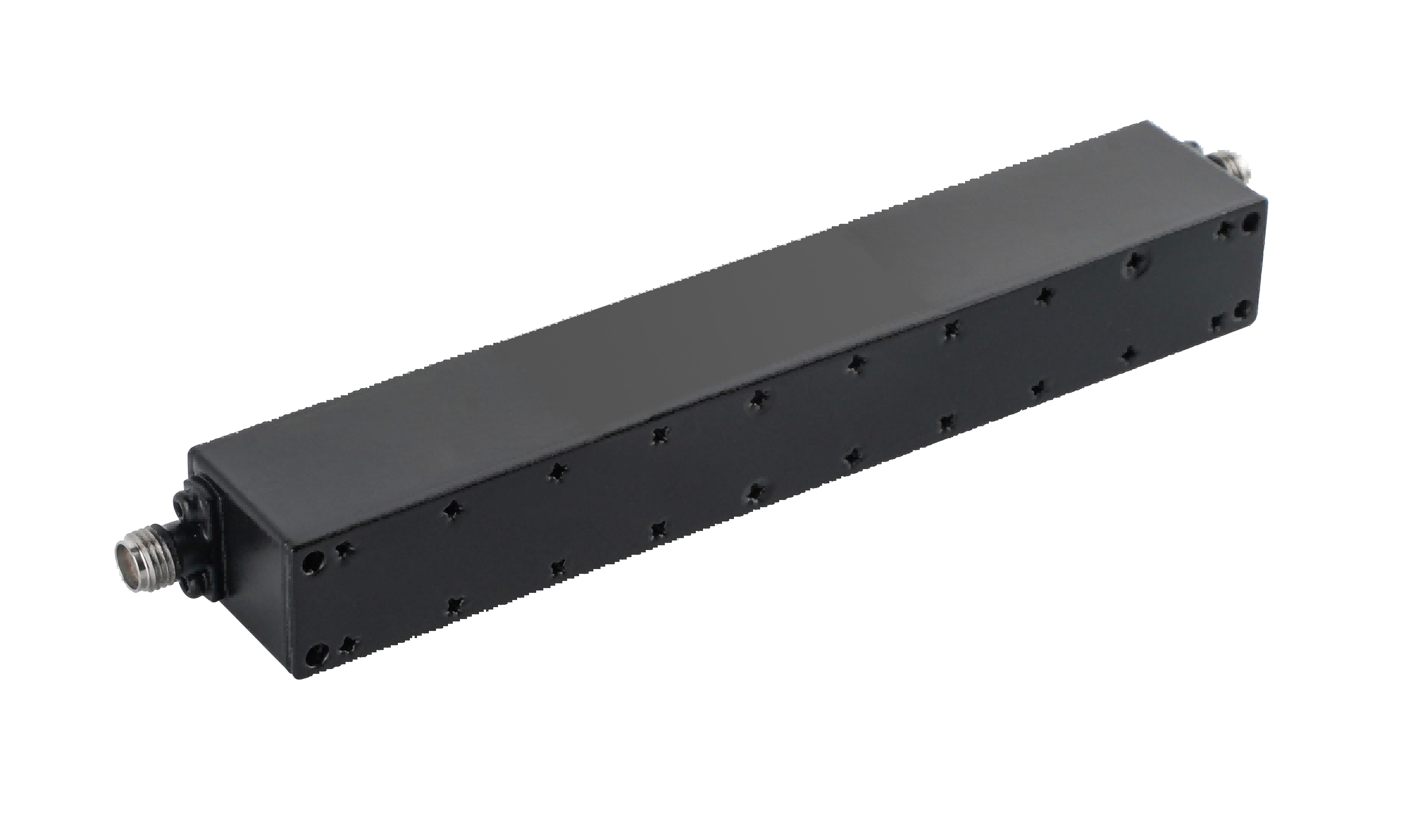 What Types of Coaxial Suspension Line Filters Are Available for RF and Microwave Systems?
 Why Are Coaxial Suspension Line Filters the Right Choice for High-Performance RF Systems?
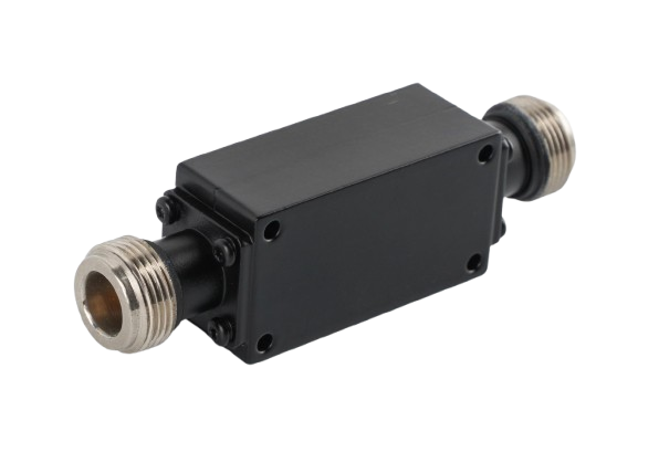
 What's the Coaxial Suspension Line Filter?
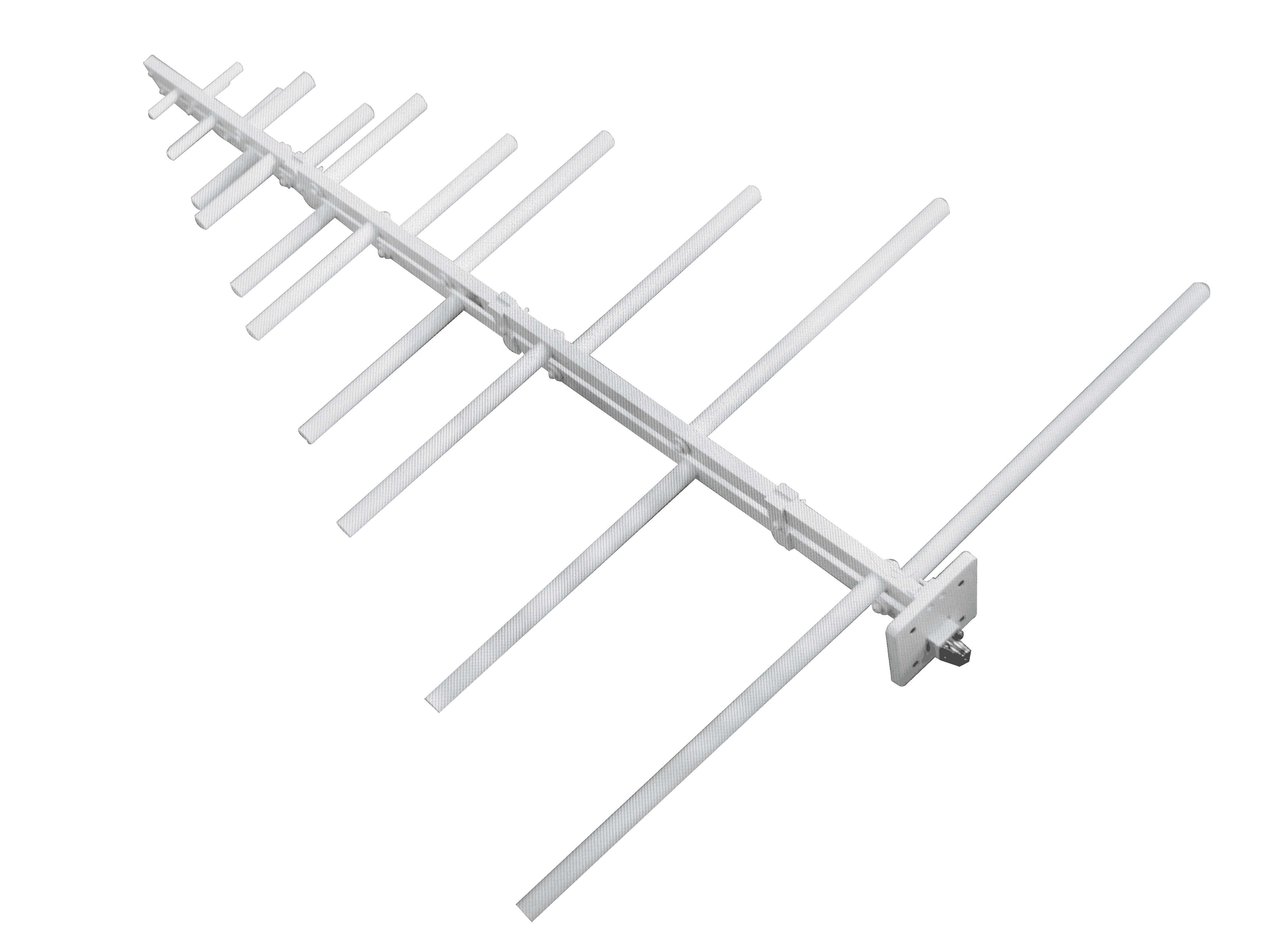 How to Choose a Log-Periodic Antenna for Long-Range Communication?