
Are You Risking Thermal Meltdown? High Power vs Standard Waveguide Loads: What’s the Difference?
High power vs standard waveguide loads: what's the difference? Learn how to manage thermal dissipation, prevent VSWR spikes, and protect your RF amplifiers.
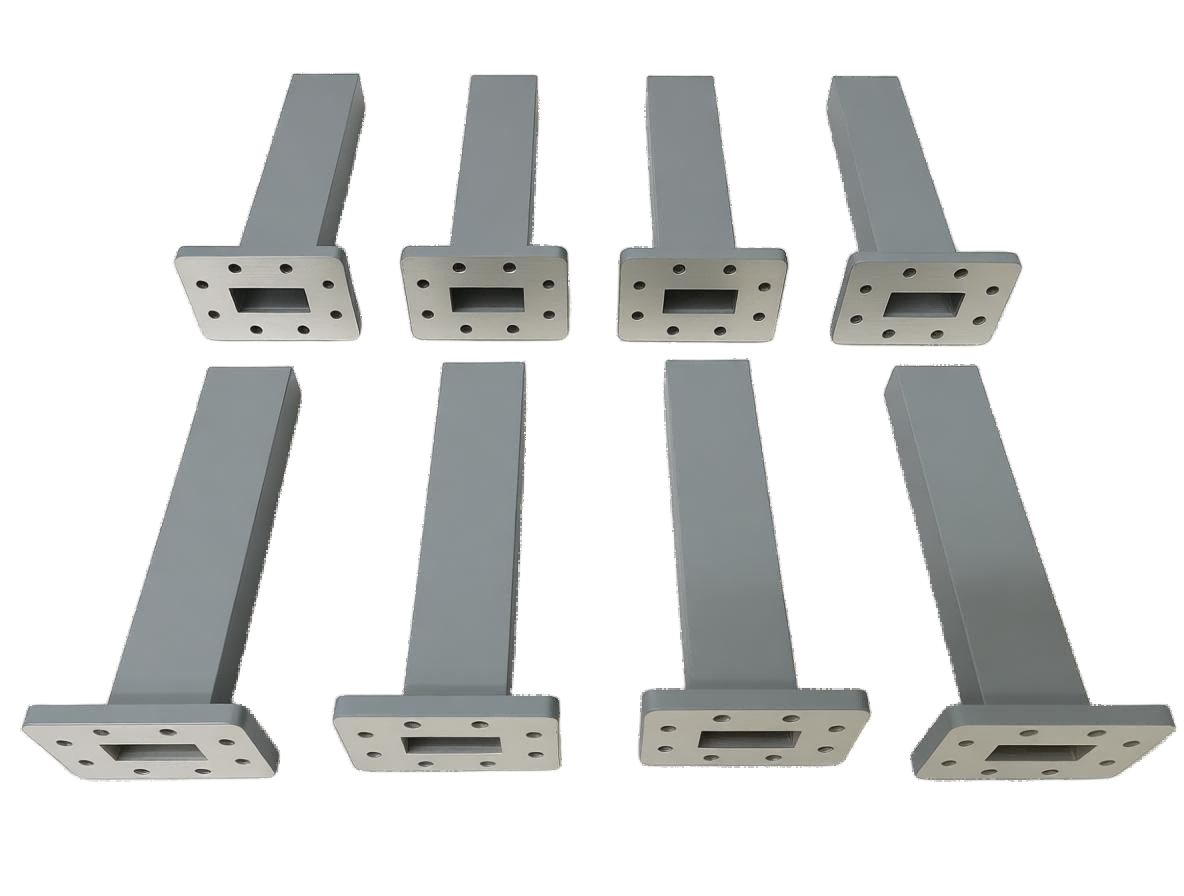
Are You Risking Thermal Meltdown? High Power vs Standard Waveguide Loads: What’s the Difference?
In the high-stakes environment of RF and microwave engineering, managing electromagnetic energy is a delicate balancing act. Whether you are integrating a commercial satellite earth station, calibrating a defense radar array, or designing a 5G mmWave backhaul, you must ensure that every milliwatt of power is strictly controlled.
When RF energy reaches an unused port or when a transmitter needs to be tested offline, that energy must be safely absorbed. If it isn't, the power reflects backward, creating severe Voltage Standing Wave Ratio (VSWR) spikes that can instantly destroy a multi-million-dollar High-Power Amplifier (HPA).
To neutralize this threat, engineers rely on waveguide loads. However, a critical point of confusion frequently leads to catastrophic system failures: misunderstanding the difference between a Standard Waveguide Load and a High Power Waveguide Load (Dummy Load).
Using a standard load in a high-power application will result in a rapid thermal meltdown, vaporizing the internal absorptive element and leaving your transmitter completely unprotected. Conversely, over-specifying a massive high-power load for a low-power port wastes valuable mechanical space and inflates your project budget.
If you are asking, "High Power vs Standard Waveguide Loads: What’s the difference?", this comprehensive guide is for you. We will decode the thermodynamics of RF absorption, explain the critical engineering trade-offs, and demonstrate how partnering with an agile, industrial-grade manufacturer can protect your equipment and keep your project timelines strictly on track.
The Physics of Absorption: Why Power Equals Heat
To understand the difference between these two components, we must first look at the fundamental physics of how a waveguide load operates. A load is designed to act as a perfect impedance match, absorbing 100% of the incident electromagnetic wave and preventing any reflection.
Inside the metallic housing lies a precisely tapered absorptive element (typically a carbon-impregnated ceramic or silicon carbide wedge). When the RF wave strikes this element, the laws of thermodynamics take over: the electromagnetic energy is entirely converted into heat.
Therefore, the distinction between a standard load and a high-power load is not just about RF performance—it is entirely about Thermal Management. If a load cannot dissipate heat faster than it absorbs it, the internal element will crack or catch fire, turning the load into an open circuit and sending lethal reflected power back into your system.
Deep Dive: Standard Waveguide Loads (Matched Terminations)
Standard waveguide loads (often referred to as low-power loads or matched terminations) are designed to absorb minimal amounts of RF energy, typically ranging from 0.5 Watts to 50 Watts Continuous Wave (CW), depending on the frequency band.
Design Characteristics:
Because the heat generated is minimal, standard loads do not require complex cooling mechanisms. They feature a smooth, compact metallic housing (usually aluminum or brass) without any external cooling fins. Their primary engineering focus is on achieving the lowest possible VSWR in the smallest possible footprint.
Primary Applications:
- Terminating Multi-Port Devices: Capping off the isolated ports of directional couplers, waveguide switches, or circulators to maintain system impedance and prevent signal leakage.
- VNA Calibration: Serving as the absolute "Match" standard in laboratory calibration kits, where ultra-low VSWR (e.g., < 1.03:1) is critical for measurement accuracy.
Deep Dive: High Power Waveguide Loads (Dummy Loads)
High Power Waveguide Loads (commonly known as Dummy Loads) are heavy-duty components engineered to absorb the full output power of a transmitter. They are rated to handle anywhere from 100 Watts to several Kilowatts of CW power.
Design Characteristics:
A high-power load is essentially a highly efficient industrial heater. To survive, it must rapidly transfer heat from the internal ceramic element to the surrounding environment. These loads are physically much larger and feature massive extruded cooling fins to maximize surface area for natural convection cooling. For extreme power levels, they may incorporate forced-air cooling (integrated fans) or liquid-cooling channels.
Primary Applications:
- Offline Transmitter Calibration: Allowing engineers to run a high-power radar or Satcom amplifier at full capacity for testing and tuning, without broadcasting interfering signals into the open air.
- 1:1 Redundancy Systems: Absorbing the output of a standby amplifier in a satellite uplink matrix, keeping the backup system warmed up and ready to take over instantly if the primary amplifier fails.
One of the most dangerous mistakes in specifying a high-power load is ignoring Peak Power. In pulsed radar systems, the Average Power (CW) might only be 100 Watts, but the Peak Power during the microsecond pulse could be 100 Kilowatts. If the load is only rated for the average power, the intense voltage of the peak pulse will ionize the air inside the waveguide, causing catastrophic electrical arcing (sparking) that will destroy the load and the transmitter. Always specify both CW and Peak power requirements!
Head-to-Head Comparison Guide
To help system integrators make quick, accurate decisions, here is a side-by-side comparison of the two components:
| Feature | Standard Waveguide Load | High Power Waveguide Load (Dummy Load) |
|---|---|---|
| Power Handling (CW) | Low (Typically 0.5W to 50W) | High (100W to multiple Kilowatts) |
| Thermal Design | Smooth housing, natural heat dissipation | Finned housing, forced air, or liquid cooling |
| Physical Size | Ultra-compact, lightweight | Large, heavy, requires adequate spatial airflow |
| Primary Engineering Focus | Ultra-low VSWR and compact footprint | Thermodynamics, heat dissipation, and peak voltage handling |
| Typical Use Case | Terminating the isolated port of a directional coupler | Absorbing the full output of a radar transmitter during testing |
Overcoming Supply Chain Fragility with Agile Manufacturing
Understanding the thermodynamic differences between standard and high-power loads is only the first step. The true challenge for system integrators today is securing these mission-critical components on time to meet strict project deadlines.
For decades, the RF industry has relied on a handful of legacy Western manufacturers. While their quality is established, their rigid, bureaucratic supply chains often result in agonizing 16 to 24-week lead times. When you are deploying a new satellite earth station or upgrading a critical EMC test bench, waiting half a year for a finned dummy load is unacceptable. It stalls projects, frustrates stakeholders, and delays your time-to-market.
You need a partner who matches your engineering rigor with manufacturing agility.
We believe that your supplier should be a strategic partner, not a bottleneck. As a professional manufacturer, AO Microwave offers deep customization capabilities for both Standard and High Power Waveguide Loads across the entire spectrum (up to 110 GHz). Whether you need an ultra-low VSWR standard load for VNA calibration, or a custom-finned dummy load optimized for high-altitude thermal derating, our engineering team can design and manufacture the exact component you need. Combined with our agile manufacturing process, we deliver these tailored, industrial-grade solutions rapidly, ensuring your project stays on schedule without compromising on equipment safety.
Conclusion: Specify with Intelligence, Protect Your Architecture
In the high-stakes world of microwave engineering, a waveguide load is the ultimate insurance policy for your signal integrity and hardware safety. By clearly understanding the difference between a Standard Load (for port isolation) and a High Power Dummy Load (for thermal dissipation), you can eliminate procurement errors, prevent catastrophic thermal meltdowns, and ensure flawless signal routing across your entire architecture.
By partnering with a manufacturer that offers advanced thermal engineering, diverse flange options, and robust customization capabilities, you empower your engineering team to innovate without limitations.
Ready to Safeguard Your RF System?
Don't let thermal failures or rigid supply chains delay your project launches. Whether you need precision Standard Loads for a Satcom routing matrix, or massive High Power Dummy Loads for radar calibration, AO Microwave has the expertise and manufacturing agility to deliver exactly what you need.
Contact our engineering team today to discuss your specific power and environmental requirements, and let us provide the perfect tailored solution for your RF system.