
Can a Microstrip Connector Replace a Cable Connector in My RF Assembly?
RF engineer confused a microstrip connector with a cable connector on an SMA assembly. Here's how to tell them apart — and why frequency ratings add another layer.
Can a Microstrip Connector Replace a Cable Connector in My RF Assembly?
Every once in a while, an RFQ lands in the inbox that looks straightforward on the surface but unravels into a teachable moment. A client recently reached out with a cable assembly request: one end standard SMA male, the other end a "custom SMA female" they'd sourced elsewhere. They had the mechanical drawings ready and the connector in hand. They just needed us to build the cable.
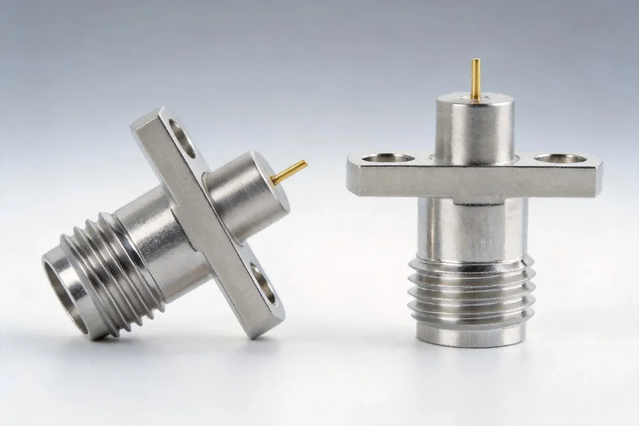
When we pulled up the drawing for that custom SMA female, something didn't add up. The part was not a cable connector at all. It was a microstrip connector — specifically, an edge-launch style meant to be soldered onto a PCB trace, not crimped or clamped onto a coaxial cable. The center pin geometry, the mounting flange, and the dielectric interface all pointed in one direction: this connector was designed to transition a signal from a coaxial interface onto a planar transmission line, not to terminate a cable.
The Board-Level Gap That Trips Up Even Experienced Engineers
It's an easy trap to fall into. From the outside, an SMA female bulkhead connector and an SMA female edge-launch microstrip connector can look nearly identical. Both have the same 1/4″-36 threaded interface. Both mate with a standard SMA male plug. But what happens on the back end — the side that connects to your signal path — is fundamentally different.
A cable connector terminates onto a coaxial cable, where the center conductor of the coax becomes the center pin of the connector, or a captive pin solders directly to it. The braided shield gets clamped or crimped to the connector body, maintaining a fully enclosed, shielded transmission line from end to end. A microstrip connector, by contrast, transitions the signal from the coaxial mode to a planar PCB trace. Its center pin extends into a launch pin that sits on a surface pad or inserts through a via. The ground reference comes from the PCB ground plane, not from a cable braid. It cannot be crimped onto a cable — there's nothing to clamp to.
We walked the client through this distinction. We sent them annotated drawings, side-by-side photos, and a brief explanation of why trying to force a microstrip connector onto a cable would result in an open circuit — or worse, a poorly matched connection that would reflect signal back and degrade the entire link budget. The client took the news well, updated their BOM, and came back with a proper cable-mount SMA female specification.
Frequency Matters Too — Each Connector Has Its Ceiling
This conversation also led naturally into a discussion about frequency. Different SMA connector variants support different maximum frequencies, and the choice between cable-mount, panel-mount, and PCB-mount styles further constrains usable bandwidth. A standard SMA connector works reliably up to 26.5 GHz. Push beyond that and you're looking at 3.5 mm (34 GHz), 2.92 mm (40 GHz), or 2.4 mm (50 GHz) interfaces.
We pointed the client to our RF Connector Frequency guide, which lays out the frequency ceiling for every common connector type in one place. It's the kind of reference that should be bookmarked if you're regularly specifying interconnects for microwave systems.
At AO Microwave, this kind of pre-production review is part of our standard workflow for custom RF cable assemblies. Catching a connector mismatch before the solder hits the iron saves weeks of rework and a lot of frustration. The global RF coaxial connector market was valued at approximately USD 1.25 billion in 2024 and is projected to reach USD 1.95 billion by 2031 (Report Prime), driven largely by 5G infrastructure and satellite communication — which means more engineers, more connector variants, and more chances for confusion.
I see SMA connectors on both cables and PCBs. Are they interchangeable?
No. The SMA interface (threaded coupling, 50 Ω impedance) is standardized, but the back-end termination is completely different. A cable-mount SMA has a crimp or clamp mechanism for coaxial cable. A PCB-mount SMA (edge-launch or surface-mount) has a launch pin designed to transition onto a microstrip or coplanar waveguide trace. They mate on the front side but cannot substitute for each other on the back side.
How do I tell if my connector is a microstrip type or a cable type?
Look at the termination side. If you see a crimp ferrule, a solder cup for a center conductor, or a clamp nut for cable braid, it's a cable connector. If you see a flat mounting flange with two screw holes, a launch pin extending outward, and no cable entry port — it's a microstrip/PCB connector.
What happens if I try to use a microstrip connector on a cable?
The center conductor won't have a proper connection to the coax center pin, and there's no way to terminate the cable shield to the connector body. The result is either an open circuit or a severely mismatched transition with high VSWR. At microwave frequencies, even a small impedance discontinuity can cause significant signal reflection.
Does SMA always support up to 26.5 GHz?
A well-manufactured precision SMA can reach 26.5 GHz, but performance depends on manufacturing tolerances, dielectric material quality, and assembly quality. In practice, many standard SMAs are rated to 18 GHz. Always check the manufacturer's spec sheet for the specific part number you're using.
What connector should I use if I need above 26.5 GHz?
For 26.5–34 GHz, consider 3.5 mm connectors (air dielectric). For 40 GHz, 2.92 mm (also known as K-connector). For 50 GHz, 2.4 mm. These are mechanically compatible with SMA but use tighter tolerances and air dielectrics to achieve higher cutoff frequencies.
Not Sure Which Connector You Need?
Tell us the connector type, your operating frequency, and the application. We'll help you pick the right part before you commit to a BOM.
Contact Our Engineering Team