
What Is a Waveguide Coupler and How Does It Work? The Ultimate Guide to RF Power Monitoring
What is a waveguide coupler? Learn how directional couplers work, compare cross-guide vs broadwall types, and optimize RF power monitoring for your next project.
What Is a Waveguide Coupler and How Does It Work? The Ultimate Guide to RF Power Monitoring
Imagine you are an RF engineer overseeing a high-power satellite earth station or a state-of-the-art EMC testing chamber. Your transmitter is pumping hundreds of watts of microwave energy toward the antenna. But how do you know exactly how much power is actually reaching the antenna? More importantly, how do you know if power is reflecting back into your expensive amplifier due to an impedance mismatch, threatening to destroy your equipment?
You cannot simply disconnect the transmission line to measure the signal—that would interrupt the system and defeat the purpose. You need a way to "peek" into the transmission line, sample a tiny, precise fraction of the microwave energy, and measure it without disrupting the main signal flow.
This is exactly where a waveguide directional coupler becomes the unsung hero of your RF architecture.
As the global microwave equipment market expands—fueled by 5G mmWave rollouts, commercial UAV data links, and advanced defense radar systems—understanding how to properly specify and utilize waveguide couplers is critical for system integrators and procurement managers. In this comprehensive guide, we will demystify what a waveguide coupler is, explain the physics of how it works, and help you choose the right industrial-grade components to protect your systems and optimize your BOM costs.

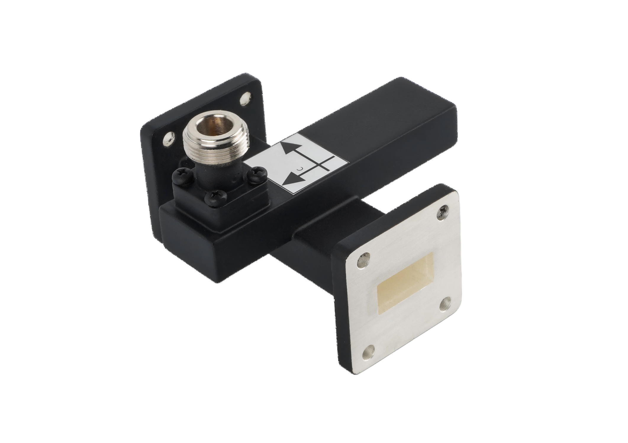
A high-precision waveguide directional coupler allows engineers to monitor forward and reflected RF power without interrupting the main transmission path.
What Is a Waveguide Coupler?
At its core, a waveguide directional coupler is a passive RF microwave component used to proportionally split or combine electromagnetic signals. It consists of two parallel (or intersecting) waveguide transmission lines placed close together, with one or more precisely machined holes (apertures) in the common wall separating them.
The primary waveguide (the "Main Line") carries the high-power signal from your transmitter to your antenna. The secondary waveguide (the "Coupled Line") captures a very small, predetermined fraction of that signal. This sampled signal is then routed to a detector, power meter, or spectrum analyzer for monitoring.
How Does a Waveguide Directional Coupler Work? (The Physics Explained)
To understand how a coupler works, we need to look at the magic of electromagnetic wave interference. Let's break down the process step-by-step:
- The Main Signal Flow: The primary microwave signal travels down the main waveguide (from Port 1 to Port 2).
- The Coupling Holes: In the wall separating the main waveguide and the secondary waveguide, there are specific holes (often spaced exactly one-quarter wavelength, or λ/4, apart). As the main signal passes these holes, a small amount of electromagnetic energy "leaks" into the secondary waveguide.
- Constructive Interference (The Coupled Port): Because of the precise spacing of the holes, the leaked waves traveling in the forward direction inside the secondary waveguide are in phase. They add up (constructive interference) and exit through the Coupled Port (Port 3). This gives you your power measurement.
- Destructive Interference (The Isolated Port): Conversely, the leaked waves traveling in the reverse direction inside the secondary waveguide are out of phase. They cancel each other out (destructive interference). Any residual energy is absorbed by a built-in matched termination load at the Isolated Port (Port 4).
This directional nature is what makes the device so valuable. It can differentiate between forward power (going to the antenna) and reflected power (bouncing back from the antenna).
4 Key Specifications You Must Know Before Ordering
When sourcing waveguide couplers for your telecom, defense, or medical applications, you cannot just guess the specs. Procurement managers and engineers must align on these four critical parameters:
1. Coupling Factor (dB)
This indicates how much of the main signal is sampled. For example, a 30 dB coupler means the signal at the coupled port is 30 decibels lower (1/1000th the power) than the main signal. If you are transmitting 1,000 Watts, the coupled port will output a safe, measurable 1 Watt. Common coupling values are 10 dB, 20 dB, 30 dB, 40 dB, and 50 dB.
2. Directivity (dB)
Directivity is the measure of the coupler's ability to isolate forward and reflected signals. It is the most critical spec for accurate VSWR measurement. A high directivity (e.g., >30 dB or >40 dB) means the coupler is extremely good at ignoring the forward signal when you are trying to measure the reflected signal. Poor directivity leads to false VSWR readings.
3. Insertion Loss
This is the amount of power lost in the main transmission line simply by inserting the coupler into the system. Because waveguides inherently have ultra-low loss, a high-quality waveguide coupler will have minimal insertion loss (often less than 0.1 dB), ensuring maximum power reaches your antenna.
4. VSWR (Voltage Standing Wave Ratio)
The coupler itself must not introduce significant reflections into your system. A low VSWR (typically < 1.10:1) ensures that the coupler is perfectly impedance-matched to your existing waveguide run.
Common Types of Waveguide Couplers
Depending on your space constraints and accuracy requirements, you will typically choose between two main designs:
| Feature | Cross-Guide Coupler | Broadwall Directional Coupler |
|---|---|---|
| Design | The secondary waveguide crosses the main waveguide at a 90-degree angle (perpendicular). | The secondary waveguide runs parallel to the main waveguide, sharing the broad wall. |
| Size & Footprint | Very compact. Ideal for tight spaces in radar systems or UAV payloads. | Longer and bulkier due to the parallel design and multiple coupling holes. |
| Directivity & Accuracy | Moderate (typically 15 dB to 20 dB). Good for basic power monitoring. | Extremely High (often >35 dB to 40+ dB). Essential for precise VSWR measurement. |
| Cost | More cost-effective and easier to manufacture. | Higher cost due to precision machining of multiple quarter-wave holes. |
The "Aerospace-Grade" Trap: How to Optimize Your BOM Costs
One of the biggest mistakes we see procurement teams make is over-specifying their RF components. There is a pervasive myth that to get high directivity and reliability, you must purchase ultra-expensive "aerospace-grade" couplers from legacy Western brands, often enduring 20-week lead times.
Unless your coupler is being launched into deep space, you are likely overpaying.
For terrestrial applications—such as 5G base stations, commercial satellite earth stations (VSAT), EMC testing laboratories, and medical linear accelerators (LINACs)—high-quality industrial-grade waveguide couplers are the perfect solution.
At AO Microwave, we specialize in manufacturing premium industrial-grade waveguides, directional couplers, and RF coaxial components. By focusing on the precise mechanical tolerances required for excellent directivity and low insertion loss, we provide components that perform flawlessly under high power. We help our clients in Europe and the Americas slash their Bill of Materials (BOM) costs and shorten lead times, without sacrificing a single decibel of performance.
If you need to monitor both forward power and reflected power simultaneously, specify a Dual Directional Coupler. This device features two secondary waveguides (or one secondary waveguide with two coupled ports), allowing you to connect a power meter to the forward port and a VSWR alarm to the reflected port at the same time, saving space and installation time.
Real-World Applications: Where Are They Used?
Waveguide couplers are indispensable in any high-frequency, high-power RF architecture. Key applications include:
- Satellite Communications (Satcom): Monitoring uplink power in C, X, Ku, and Ka bands to ensure the signal is strong enough to reach the satellite without overloading the amplifier.
- EMC / EMI Testing: In anechoic chambers, couplers are used to sample the exact RF field strength being directed at the device under test (DUT), ensuring compliance with international standards.
- Defense and Weather Radar: Sampling the high-power transmitter pulse to trigger receiver timing circuits or to monitor the health of the radar antenna.
- Medical Equipment: In radiation therapy machines (LINACs), couplers monitor the high-power S-band microwaves used to accelerate electrons, ensuring precise patient dosing.
Conclusion: Protect Your System with the Right Coupler
A waveguide directional coupler is much more than just a piece of machined metal; it is the diagnostic heart of your RF system. By allowing you to accurately monitor forward power and detect dangerous reflected power, it protects your expensive amplifiers and ensures your system operates at peak efficiency.
When selecting a coupler, understanding the balance between coupling factor, directivity, and physical design (Cross-Guide vs. Broadwall) is crucial. More importantly, partnering with a reliable manufacturer of industrial-grade components can help you achieve world-class RF performance while keeping your supply chain agile and cost-effective.
Ready to Optimize Your RF Power Monitoring?
Don't let poor VSWR monitoring or overpriced components put your projects at risk. Whether you need a compact Cross-Guide coupler for a UAV data link or a high-directivity Broadwall coupler for an EMC lab, AO Microwave has the industrial-grade solutions you need.
Contact our engineering sales team today for a technical consultation or a custom quote, and let us help you build a more reliable, cost-effective RF system.