
Are Microscopic Errors Corrupting Your 110 GHz Data? Why Precision Matters in Millimeter-Wave Waveguide Loads
Why does precision matter in millimeter-wave waveguide loads? Learn how CNC accuracy prevents VSWR spikes and corrupted VNA data in RF systems up to 110 GHz.
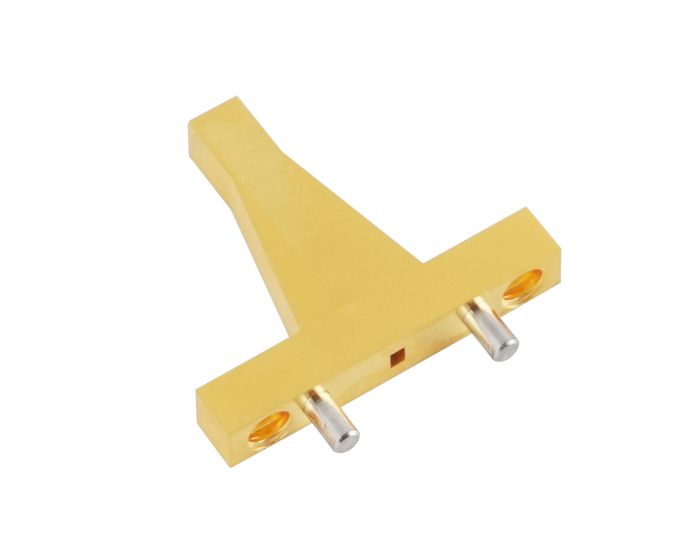
Are Microscopic Errors Corrupting Your 110 GHz Data? Why Precision Matters in Millimeter-Wave Waveguide Loads
As the RF and microwave industry aggressively expands into the millimeter-wave (mmWave) spectrum—driven by 6G research, high-resolution automotive radar, and advanced aerospace imaging—engineers are operating at the absolute edge of physical limits. At frequencies like 75 GHz or 110 GHz, the margin for error does not simply shrink; it vanishes entirely.
When setting up a Vector Network Analyzer (VNA) for a critical W-band measurement, or when isolating a high-frequency transceiver module, your system requires a perfect impedance match to prevent signal reflection. This is the job of the waveguide load (or matched termination).
At lower frequencies, a slightly misaligned absorptive element might only cause a negligible drop in performance. But in the mmWave spectrum, the physics change dramatically. A machining error of just a few micrometers—thinner than a human hair—will trigger massive Voltage Standing Wave Ratio (VSWR) spikes. If your load reflects even a fraction of the signal, your VNA calibration is fundamentally flawed, rendering weeks of expensive research and measurement data completely useless.
If you are asking, "Why does precision matter so much in millimeter-wave waveguide loads?", the answer lies in the unforgiving nature of short wavelengths. In this comprehensive guide, we will explore the electromagnetic physics of mmWave absorption, detail the three critical areas where manufacturing precision is non-negotiable, and demonstrate how partnering with an agile, industrial-grade manufacturer can safeguard your signal integrity.
The Physics of mmWave: Why Wavelength Dictates Tolerance
To understand the absolute necessity of precision, we must look at the relationship between frequency and wavelength. As frequency increases, the physical length of the electromagnetic wave decreases proportionally.
- At 3 GHz (S-Band), the wavelength in free space is approximately 100 mm. A machining tolerance of 0.1 mm is only 0.1% of the wavelength. The electromagnetic wave barely "notices" the imperfection.
- At 110 GHz (W-Band), the wavelength shrinks to a microscopic 2.7 mm. That same 0.1 mm machining error is now nearly 4% of the wavelength. To the electromagnetic wave, that tiny burr or misalignment looks like a massive brick wall.
When the wave hits this "wall" inside the termination, it reflects backward. To prevent this, engineers must source precision waveguide loads that are CNC-machined to exact micrometer tolerances, ensuring the wave is smoothly and entirely absorbed without any impedance disruption.
3 Critical Manufacturing Pillars for mmWave Waveguide Loads
To achieve a near-perfect VSWR at frequencies up to 110 GHz, a waveguide load must be manufactured with uncompromising precision in three specific areas:
1. The Geometry of the Absorptive Element
You cannot simply place a flat block of resistive material inside a waveguide; the sudden change in impedance would cause immediate reflection. The absorptive element (typically a carbon-impregnated ceramic) must be precisely tapered into a wedge or pyramid shape.
At W-band (WR-10), the internal dimensions of the waveguide are a mere 2.54 mm x 1.27 mm. Machining a fragile ceramic taper to fit perfectly inside this microscopic cavity—without touching the walls and altering the capacitance—is an extreme engineering challenge. Premium manufacturers utilize advanced 3D electromagnetic simulation combined with ultra-precise milling to ensure the taper provides a flawless, reflectionless transition.
2. Internal Surface Finish and the Skin Effect
At high frequencies, alternating current does not flow through the entire cross-section of the metal housing. Due to the Skin Effect, the current is forced to the extreme outer layer of the waveguide's inner wall. At 110 GHz, this "skin depth" is incredibly thin.
If the internal surface of the load housing has CNC chatter marks, scratches, or a rough finish, the electrical path becomes highly resistive before the wave even reaches the absorptive element. This can cause unpredictable phase shifts and signal degradation. High-frequency loads require a mirror-like internal surface finish to ensure absolute signal stability.
At 75 GHz or 110 GHz, standard flat flanges are no longer sufficient. If the flange faces are not perfectly flat, microscopic air gaps will form when bolted together. At these frequencies, RF energy will leak out of these gaps, causing massive measurement errors and degrading the load's VSWR. Millimeter-wave loads must utilize precision anti-cocking flanges (such as the UG-387/U) with exact alignment pins to guarantee a flush, leak-proof mechanical seal every single time.
Overcoming Supply Chain Fragility with Agile Manufacturing
Designing a flawless mmWave test bench or radar architecture is a significant engineering achievement. However, securing these ultra-precision components on time is often the greatest hurdle.
For decades, the industry has endured 16 to 24-week lead times from legacy Western manufacturers for high-frequency waveguide loads. When you are racing to deploy a new automotive radar system or upgrade a VNA calibration kit, waiting half a year for a WR-10 termination is unacceptable. It stalls innovation, frustrates stakeholders, and delays your time-to-market.
You need a partner who matches your engineering rigor with manufacturing agility.
We believe that your supplier should be a strategic partner, not a bottleneck. As a true source manufacturer, AO Microwave possesses the advanced CNC capabilities to support the entire spectrum—from 0.32 GHz all the way up to 110 GHz. We proudly achieve a maximum VSWR of just 1.15:1 at 110 GHz, providing research laboratories with the absolute precision required for W-band testing. Combined with our agile manufacturing process, we deliver these tailored, industrial-grade solutions rapidly, ensuring your project stays on schedule without compromising on signal integrity.
Conclusion: Demand Precision, Ensure Performance
In the unforgiving realm of millimeter-wave engineering, a waveguide load is far more than a simple end-cap; it is the ultimate reference standard for your entire system. At frequencies up to 110 GHz, microscopic machining errors in the absorptive taper, surface finish, or flange alignment will inevitably lead to VSWR spikes and corrupted data.
By understanding the physics of mmWave absorption and partnering with a manufacturer that possesses the advanced capabilities to deliver true industrial-grade precision, you empower your engineering team to innovate with absolute confidence.
Ready to Achieve Flawless mmWave Absorption?
Don't let microscopic machining errors corrupt your measurement data, and don't let rigid supply chains delay your project launches. Whether you need robust loads for Ka-band Satcom or ultra-precision WR-10 loads for 110 GHz VNA calibration, AO Microwave has the expertise and manufacturing agility to deliver exactly what you need.
Contact our engineering team today to discuss your specific frequency requirements, and let us provide the perfect tailored solution for your RF architecture.