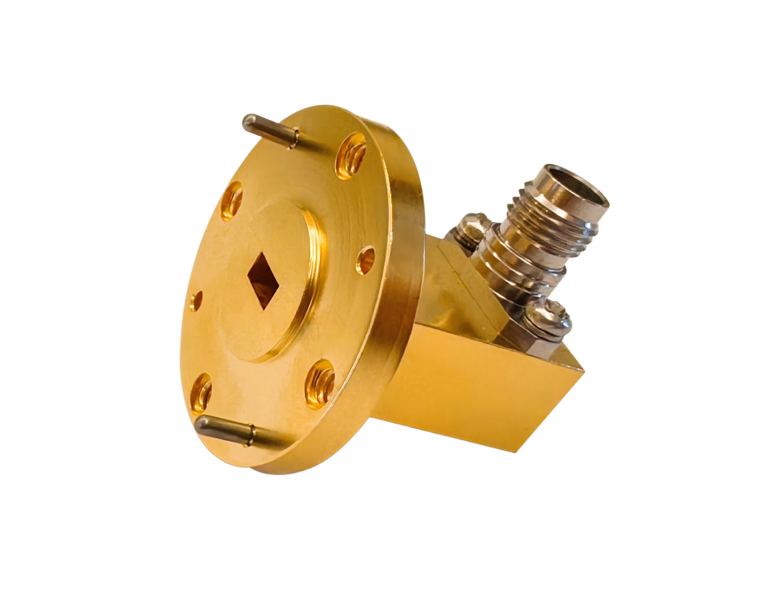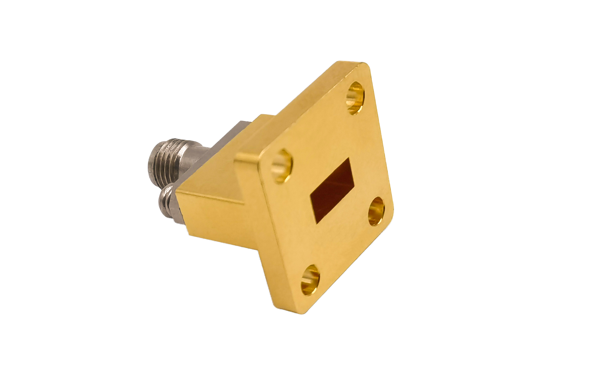
Waveguide Load
Waveguide Load terminations absorb microwave energy with low VSWR and high power handling. Used in radar transmitters, RF test laboratories, satellite communication systems, microwave transmitters and high-frequency measurement equipment.
Precision Waveguide Loads for Low-Reflection Terminations
AO Microwave’s waveguide loads (matched terminations) are designed to absorb incoming electromagnetic energy with minimum signal reflection, acting as matched loads to terminate unused transmission ports. Operating up to 110 GHz, our terminations are offered in lightweight aluminum and high-power copper bodies with black-anodized or high-emissivity external finishes to optimize passive heat transfer. For precision laboratory and VNA calibration setups, our low-power calibration loads deliver an exceptional return loss of > 35 dB (VSWR < 1.03:1), while our ruggedized medium and high-power termination loads handle up to 500W+ CW in active system paths.
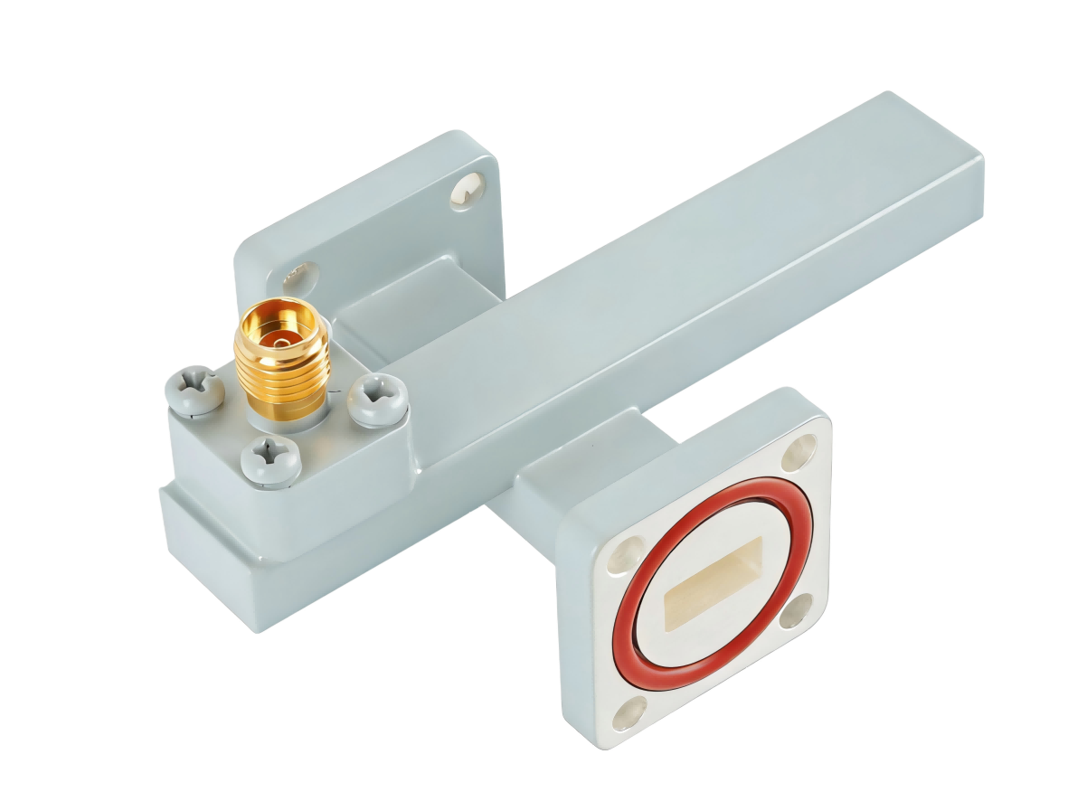
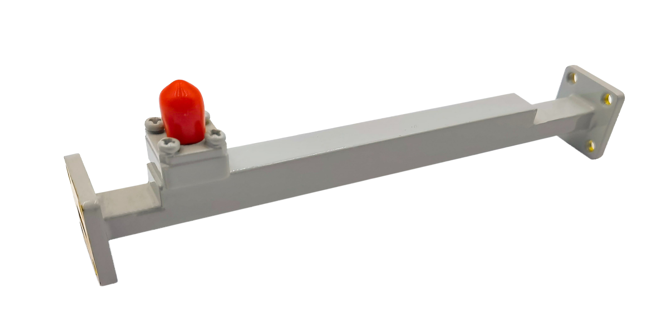
By utilizing premium, fully cured absorbing ceramics with precise linear tapers, our loads provide stable impedance matching across standard bands from WR-90 to WR-10. These devices are critical for terminating isolate ports in circulators, protecting active components in transmitter paths, and establishing reliable reflection references.
| Part No | Frequency/GHz | VSWR (Max) | Average Power/W (Max) | Flange Type |
|---|---|---|---|---|
| AO2300-WL1.05PACG-20W | 0.32-0.49 | 1.05 | 20 | UDR3 |
| AO2100-WL1.05PACG-20W | 0.35-0.53 | 1.05 | 20 | UDR4 |
| AO1800-WL1.05PACG-15W | 0.41-0.62 | 1.05 | 15 | UDR5 |
| AO1500-WL1.05PACG-15W | 0.49-0.75 | 1.05 | 15 | UDR6 |
| AO1150-WL1.05PACG-15W | 0.64-0.98 | 1.05 | 15 | UDR8 |
| AO975-WL1.05PACG-15W | 0.75-1.15 | 1.05 | 15 | UDR9 |
| AO770-WL1.03PACG-10W | 0.96-1.46 | 1.03 | 10 | UDR12 |
| AO650-WL1.03PACG-10W | 1.13-1.73 | 1.03 | 10 | UDR14 |
| AO510-WL1.03PACG-10W | 1.45-2.20 | 1.03 | 10 | UDR18 |
| AO430-WL1.03PACG-10W | 1.72-2.61 | 1.03 | 10 | UDR22 |
| AO340-WL1.03PACG-5W | 2.17-3.30 | 1.03 | 5 | UDR26 |
| AO284-WL1.03PACG-5W | 2.60-3.95 | 1.03 | 5 | UDR32 |
| AO229-WL1.03PACG-5W | 3.22-4.90 | 1.03 | 5 | UDR40 |
| AO187-WL1.03PACG-5W | 3.94-5.99 | 1.03 | 5 | UDR48 |
| AO159-WL1.03PACG-5W | 4.64-7.05 | 1.03 | 5 | UDR58 |
| AO137-WL1.03PCSG-5W | 5.38-8.17 | 1.03 | 5 | UDR70 |
| AO112-WL1.03PCSG-5W | 6.57-9.99 | 1.03 | 5 | UBR84 |
| AO90-WL1.03PCSG-2W | 8.20-12.5 | 1.03 | 2 | UBR100 |
| AO75-WL1.03PCSG-2W | 9.84-15.0 | 1.03 | 2 | UBR120 |
| AO62-WL1.03PCSG-2W | 11.9-18.0 | 1.03 | 2 | UBR140 |
| AO51-WL1.03PCSG-2W | 14.5-22.0 | 1.03 | 2 | UBR180 |
| AO42-WL1.03PCSG-1W | 17.6-26.7 | 1.03 | 1 | UBR220 |
| AO34-WL1.03PCSG-1W | 21.7-33.0 | 1.03 | 1 | UBR260 |
| AO28-WL1.03PCSG-1W | 26.5-40.0 | 1.03 | 1 | UBR320 |
| AO22-WL1.15PCG-0.5W | 33.0-50.0 | 1.15 | 0.5 | UG-383/U |
| AO19-WL1.15PCG-0.5W | 40.0-60.0 | 1.15 | 0.5 | UG383/UM |
| AO15-WL1.15PCG-0.5W | 50.0-75.0 | 1.15 | 0.5 | UG385/U |
| AO12-WL1.15PCG-0.5W | 60.0-90.0 | 1.15 | 0.5 | UG-387/U |
| AO10-WL1.15PCG-0.5W | 75.0-110.0 | 1.15 | 0.5 | UG387/UM |
Thermal Outgassing & Vacuum Compatibility in Space Applications
When waveguide loads operate in spacecraft payloads or deep space-vacuum chambers, they are subject to extreme conditions. High continuous RF power causes the absorbing element to generate intense localized heat, which must be dissipated through conduction. Under these vacuum conditions, standard waveguide loads made with epoxy-bound absorbers can experience thermal outgassing, releasing volatile condensable materials that can deposit on delicate optical lenses or cause RF corona breakdown in the feed network.
Furthermore, if the thermal expansion coefficient of the absorber wedge differs significantly from the waveguide housing, thermal stress can cause the absorber to crack or detach under thermal cycling. AO Microwave addresses these aerospace challenges by using specialized inorganic, non-outgassing ceramic absorbers that are mechanically matched to the expansion rates of our copper and aluminum housings. This construction provides stable heat transfer, maintains vacuum integrity, and prevents physical fracturing under thermal load.
How to Select the Right Load Profile
- Precision Calibration Loads: Designed with a long, gradual internal taper to minimize impedance mismatch, achieving a low VSWR (< 1.03) for precision laboratory measurements.
- Rugged High-Power Loads: Engineered with dense ceramic elements and integrated cooling fins (or liquid-cooling ports) to handle active transmitter paths up to 500W+ CW.
- Isolator Port Terminations: Terminate isolate ports in high-power circulators, protecting active amplifiers by absorbing high levels of reflected power.
Waveguide Load FAQs
Need reliable Waveguide Termination Loads?
Specify your WR size, continuous power (Watts), flange style, and quantity — we'll quote in 24 hours.