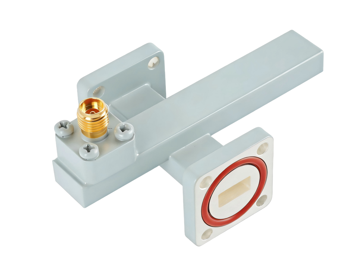
Crossguide Directional Coupler
Crossguide Directional Coupler offers high directivity and accurate microwave signal sampling for power monitoring and measurement. Widely used in radar transmitters, satellite communication systems and RF microwave test equipment.
High-Directivity Crossguide Directional Couplers
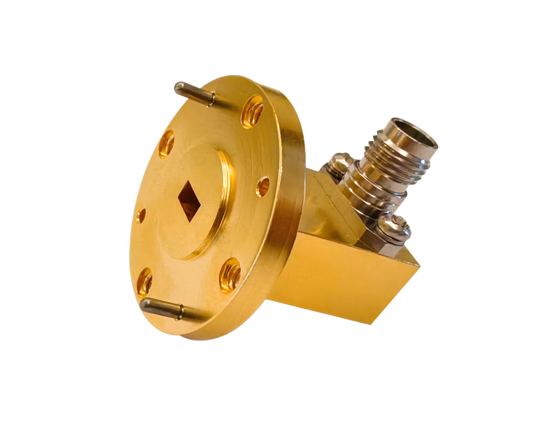
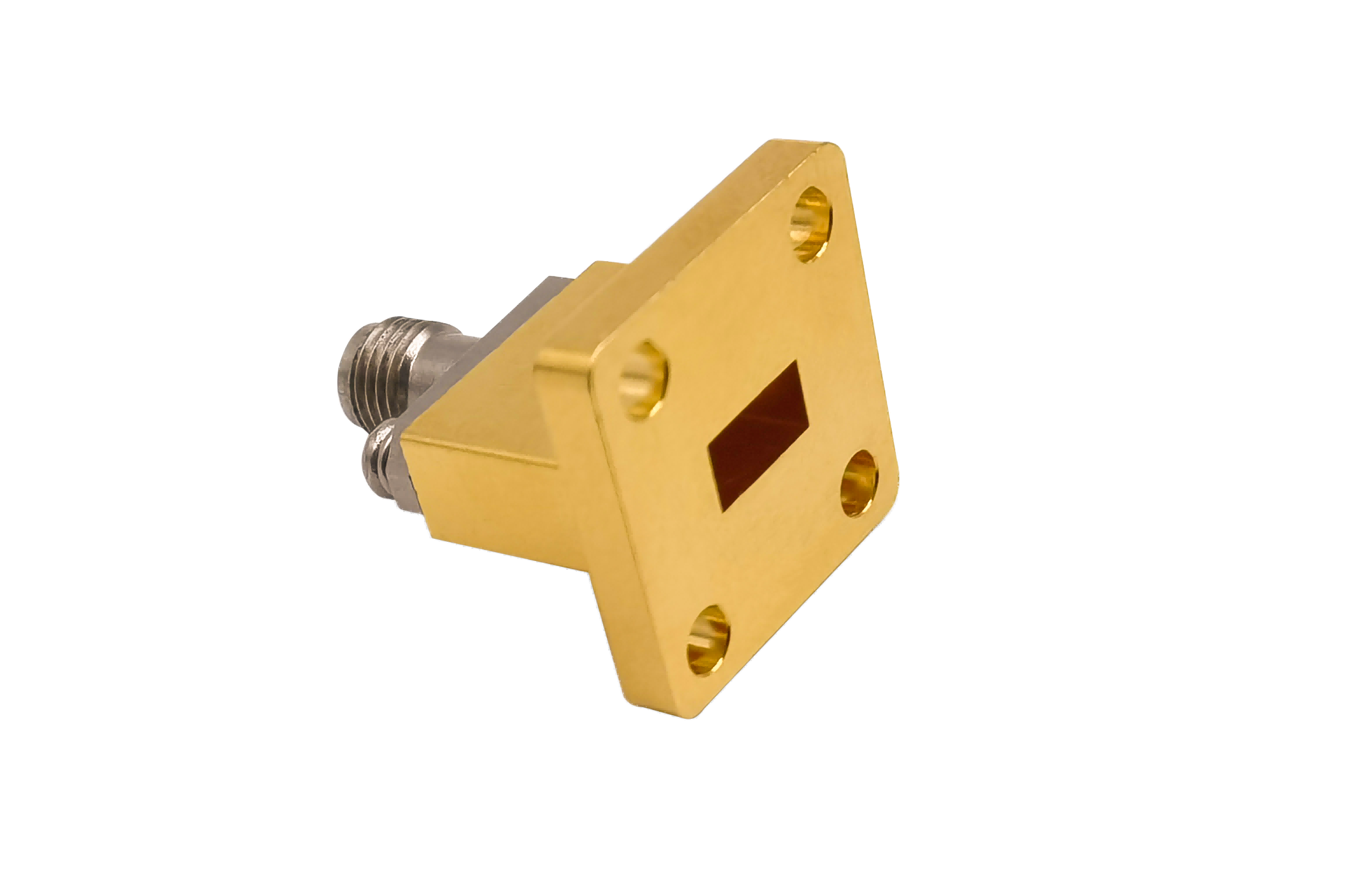
AO Microwave’s crossguide directional couplers provide signal monitoring and power sampling perpendicular to the main-line waveguide. Precision-machined from lightweight aluminum and high-power copper alloys, our couplers are available in both 3-port (with integrated low-reflection load) and 4-port (dual-directional) configurations. Available across standard bands up to 110 GHz with coupling values of 20 dB, 30 dB, or 40 dB, these couplers maintain low insertion loss on the main line and deliver a high directivity of typically > 20 dB.
These orthogonal couplers are key components for real-time power monitoring and feedback loops in active transmitter systems. Our crossguide design offers a compact, space-saving alternative to long broadwall couplers, allowing for easy integration into tightly spaced radar feeds and satellite ground station transceivers.
| Part No | Frequency/GHz | Main VSWR (Max) | Sec VSWR (Max) | IL/dB (Max) | Coupling Optional/dB | Directivity/dB (Min) | Flange Type | Connector Type |
|---|---|---|---|---|---|---|---|---|
| AO770-WL+CXNKPPACG | 0.96-1.46 | 1.1 | 1.25 | 0.2 | 20~60 | 15 | UDR12 | N Female |
| AO650-WL+CXNKPPACG | 1.13-1.73 | 1.1 | 1.25 | 0.2 | 20~60 | 15 | UDR14 | N Female |
| AO510-WL+CXNKPPACG | 1.45-2.20 | 1.1 | 1.25 | 0.2 | 20~60 | 15 | UDR18 | N Female |
| AO430-WL+CXNKPPACG | 1.72-2.61 | 1.1 | 1.25 | 0.2 | 20~60 | 15 | UDR22 | N Female |
| AO340-WL+CXNKPPACG | 2.17-3.30 | 1.1 | 1.25 | 0.2 | 20~60 | 15 | UDR26 | N Female |
| AO284-WL+CXNKPPACG | 2.60-3.95 | 1.1 | 1.25 | 0.2 | 20~60 | 15 | UDR32 | N Female |
| AO229-WL+CXNKPPACG | 3.22-4.90 | 1.1 | 1.25 | 0.2 | 20~60 | 15 | UDR40 | N Female |
| AO187-WL+CXNKPPACG | 3.94-5.99 | 1.1 | 1.25 | 0.2 | 20~60 | 15 | UDR48 | N Female |
| AO159-WL+CXNKPPACG | 4.64-7.05 | 1.1 | 1.25 | 0.2 | 20~60 | 15 | UDR58 | N Female |
| AO137-WL+CXNKPPCSG | 5.38-8.17 | 1.1 | 1.25 | 0.3 | 20~60 | 15 | UDR70 | N Female |
| AO112-WL+CXNKPPCSG | 6.57-9.99 | 1.1 | 1.25 | 0.3 | 20~60 | 15 | UBR84 | N Female |
| AO90-WL+CXNKPPCSG | 8.20-12.5 | 1.1 | 1.25 | 0.3 | 20~60 | 15 | UBR100 | N Female |
| AO75-WL+CXNKPPCSG | 9.84-15.0 | 1.1 | 1.25 | 0.3 | 20~60 | 15 | UBR120 | N Female |
| AO62-WL+CXSKPPCSG | 11.9-18.0 | 1.1 | 1.25 | 0.3 | 20~60 | 15 | UBR140 | SMA Female |
| AO51-WL+CXSKPPCSG | 14.5-22.0 | 1.1 | 1.25 | 0.3 | 20~60 | 15 | UBR180 | SMA Female |
| AO42-WL+CX2.92KPPCSG | 17.6-26.7 | 1.1 | 1.5 | 0.3 | 20~60 | 15 | UBR220 | 2.92mm Female |
| AO34-WL+CX2.92KPPCSG | 21.7-33.0 | 1.1 | 1.5 | 0.3 | 20~60 | 15 | UBR260 | 2.92mm Female |
| AO28-WL+CX2.92KPPCSG | 26.5-40.0 | 1.1 | 1.5 | 0.3 | 20~60 | 15 | UBR320 | 2.92mm Female |
The Physics of Coupling & Directivity in Crossguide Designs
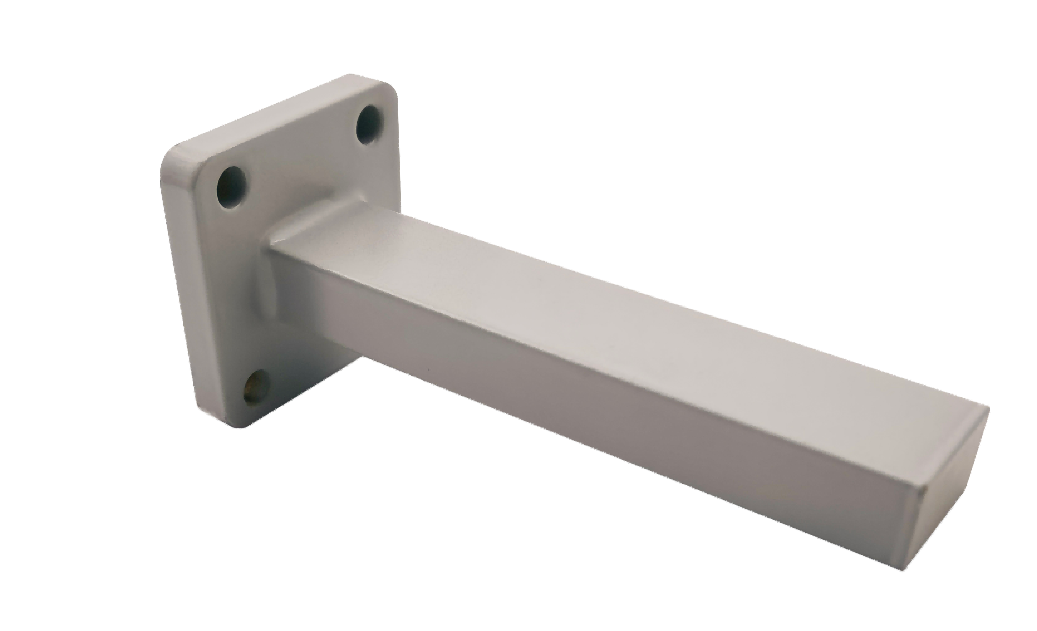
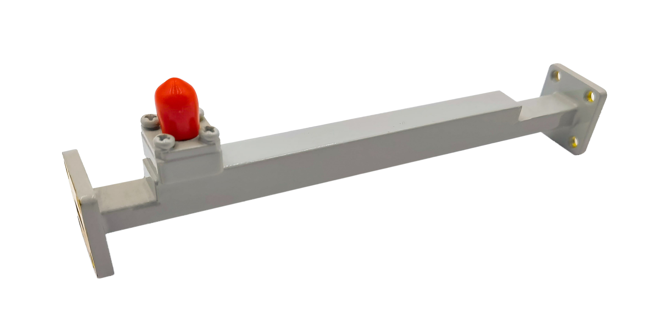
Crossguide couplers consist of two waveguides joined perpendicularly, sharing a common wall with precision apertures. These apertures allow a fraction of the electromagnetic energy in the main waveguide to couple into the auxiliary waveguide. Our couplers utilize a multi-hole design based on the Bethe-hole coupling principle, where the physical size, shape, and spacing of the coupling holes are optimized to cancel out the reverse-propagating wave while constructively adding the forward wave in the coupled port.
Maintaining high directivity is a key design challenge for these couplers. If the apertures are slightly misaligned or contain machining burrs, the reverse wave will not cancel correctly, causing signal leakage into the isolated port and degrading directivity. AO Microwave uses high-precision CNC machining to ensure consistent aperture sizing and alignment within ±0.01 mm, keeping directivity values high across the full operating band.
Main-Line Power Handling & Low Insertion Loss
- High Peak-Power Capability: Built with no internal probe pins, our copper-bodied couplers can safely handle the high peak powers found in pulsed radar systems without risk of arcing.
- Negligible Main-Line Loss: Draws only a tiny fraction of main-line power (e.g., only 0.1% for a 30 dB coupler), keeping main-line insertion loss extremely low (typically < 0.05 dB).
- Flat Coupling Response: Optimized multi-hole configurations maintain a flat coupling response across full waveguide bands, preventing calibrated power measurement errors.
Crossguide Directional Coupler FAQs
Need high-directivity Crossguide Directional Couplers?
Specify your WR size, coupling factor (20/30/40 dB), port configuration, and flanges — we'll quote in 24 hours.