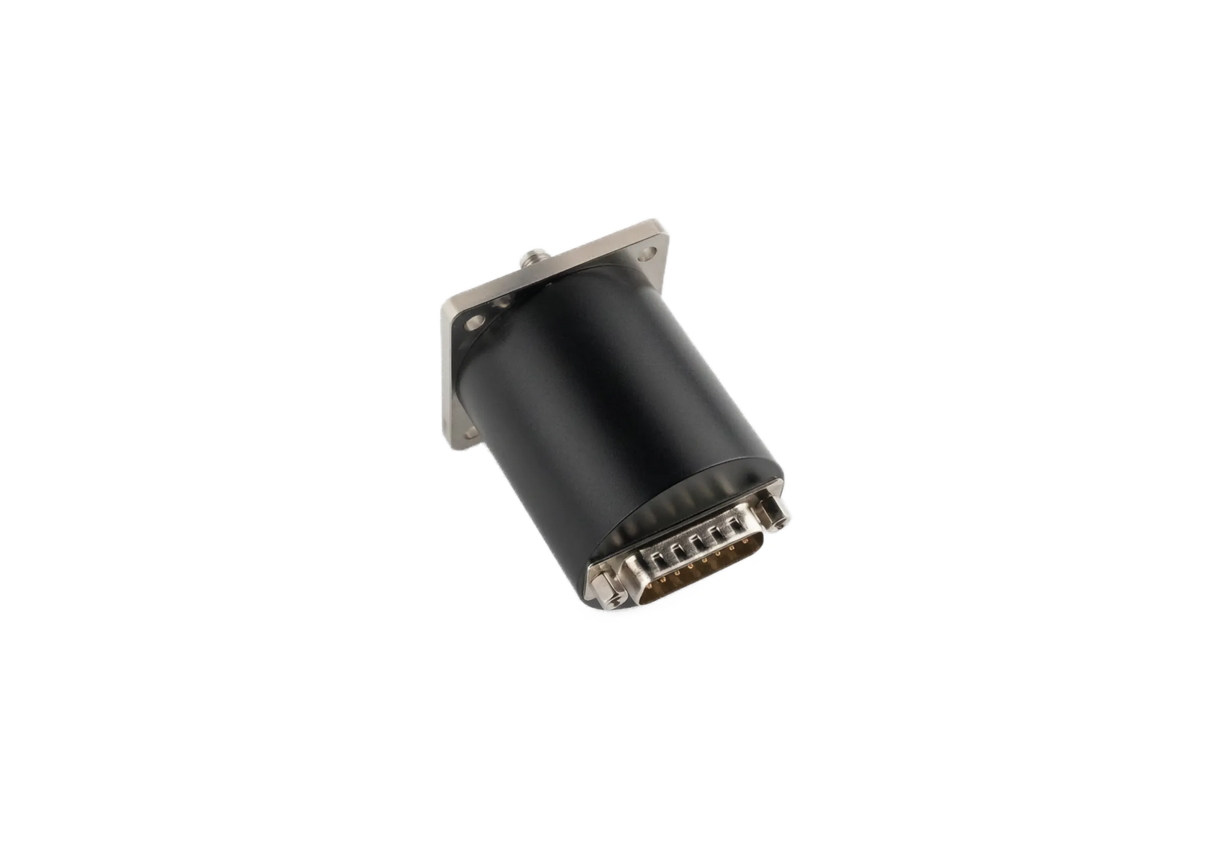
Latching or Failsafe Waveguide Switch: What Happens When the Power Dies?
Latching vs failsafe waveguide switch: what the RF path must be when power dies, the T versus TA control circuit, and a decision table for your redundant build.
Latching vs failsafe waveguide switch: what the RF path must be when power dies, the T versus TA control circuit, and a decision table for your redundant build.

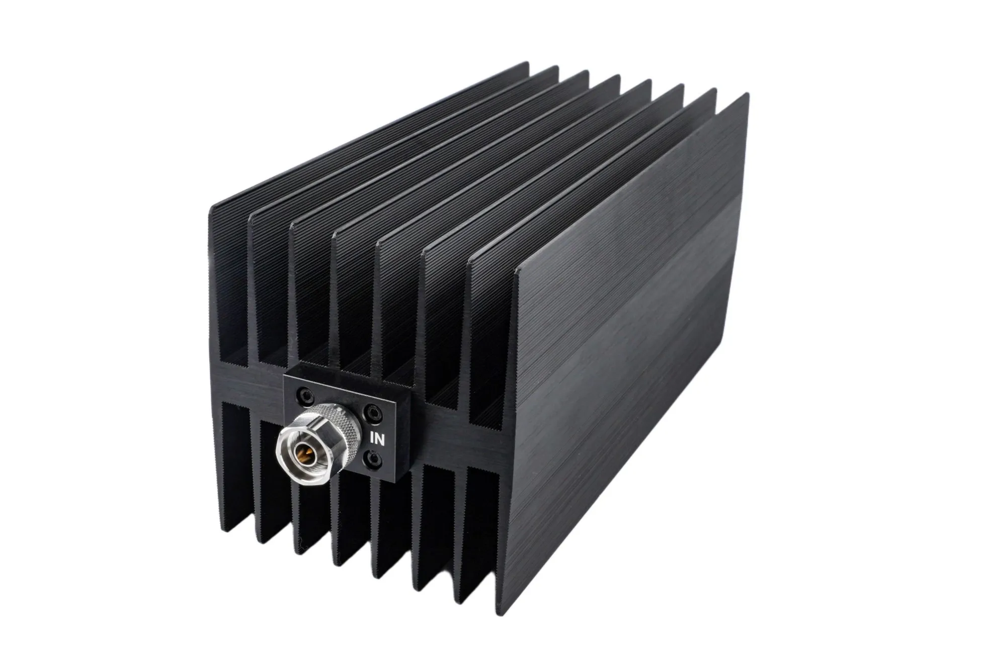
Coaxial fixed attenuator and load manual: impedance matching, CW vs peak power, IEC 61000-4-3 and MIL-STD-461 demand, derating rules, plus FAQs that prevent burnout.

Save time on complex RF math. This dBm to Power conversion table (+60 to -20 dBm) offers engineers a fast, reliable reference to ensure precision in every power measurement and link budget.

Streamline your RF design workflow with this precise VSWR to Return Loss conversion table. Built for engineers to simplify impedance matching and link budget calculations from 1.01 to 20.0 Accuracy.

Optimize RF systems with our ultimate RF connector frequency guide. Master microwave bands from F type to 1.0mm for precision engineering.

Optimize your RF systems with our ultimate microwave frequency bands guide. Covering standard ranges from HF to W-band, we bridge the gap between precise wavelengths and core waveguide flanges.

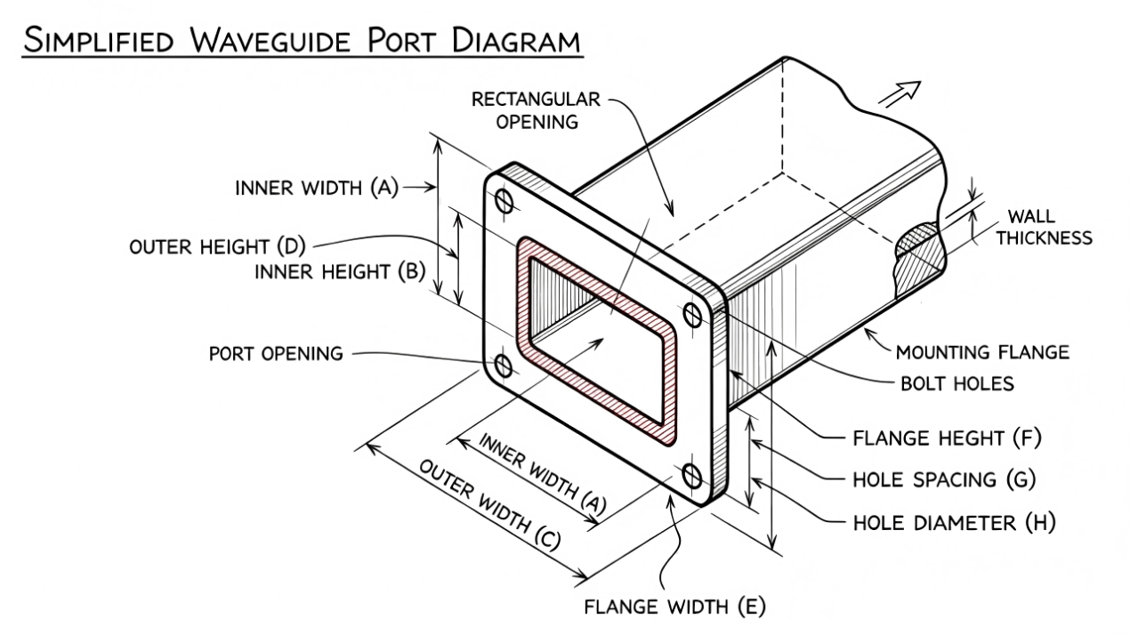
Explore standard rectangular waveguide flange types (CPRF, UBR, UAR). Compare EIA vs IEC standards, hole patterns, and engineering applications with our clear visual guide.

Waveguide size chart for standard rectangular waveguides (BJ3 to BJ900 / WR-2300 to WR-10): frequency ranges, inner dimensions, flanges and theoretical attenuation.