
Latching or Failsafe Waveguide Switch: What Happens When the Power Dies?
Latching vs failsafe waveguide switch: what the RF path must be when power dies, the T versus TA control circuit, and a decision table for your redundant build.
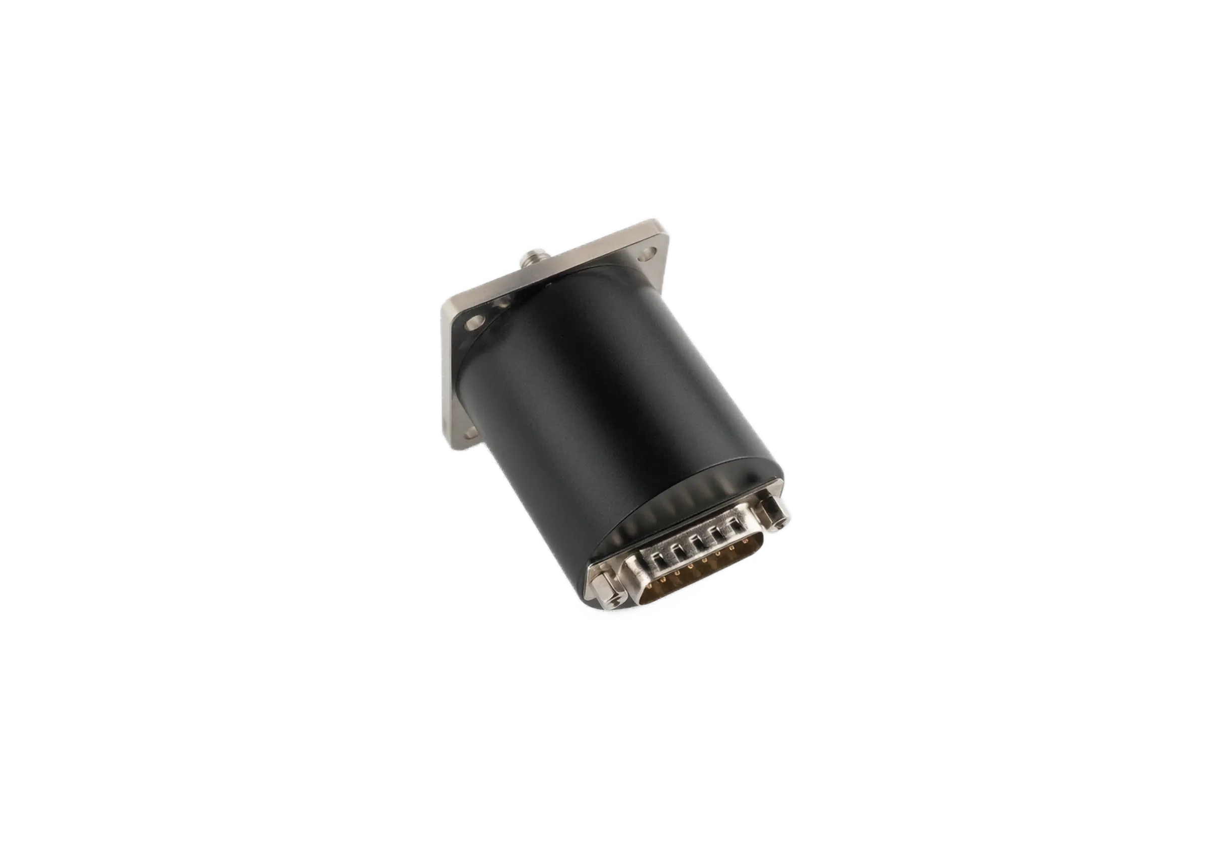
Latching or Failsafe Waveguide Switch: What Happens When the Power Dies?
The word "switch" hides a second decision that most spec sheets mention in a single line and most engineers regret later. When the cabinet loses control power, does the RF path hold its last state, or does it snap to a default? That choice is the difference between latching and failsafe, and it is decided by what your system must do during an outage, not by which actuator is cheaper.
Define the Two, Precisely
A latching switch takes a short pulse of control power to move the rotor and then holds that position with no holding current. It is the lower-cost option, it allows a manual override, and it carries the higher mean time between failures because there is no spring constantly loaded against the mechanism.
A failsafe switch returns to a spring-loaded default the instant control power disappears, which means it needs continuous current to hold the active state. It costs more, it usually cannot take a manual override, and its mean time between failures is lower because the spring is always working. One reference point from a long-running switch maker puts the commercial mix at about 98 percent latching and 2 percent failsafe, so the default in this industry is latching unless the application forces the other way.
The life numbers follow the mechanism. Latching types are rated beyond one million mechanical cycles because nothing is loaded between throws. Failsafe types exercise the return spring on every single cycle, so their rated life is lower and the spring is the part that eventually drifts. When you specify failsafe, you are accepting that wear trade in exchange for a guaranteed default with no logic and no battery.
The Real Question: What Must the Path Be When Power Fails?
This is the only question that settles the choice. If losing power must produce a known safe route, choose failsafe. The classic case is a transmitter that has to drop onto a dummy load the moment the controller goes dark, so a receiver downstream never sees a hot port. The spring does the right thing with no logic and no battery.
If the last commanded state must be preserved, choose latching. A latching switch rides out a power blink and comes back in the same position it left, which matters when re-establishing the path automatically is more important than forcing a default. It also avoids dissipating holding current inside an enclosure that is already warm, which is why the WR-22 DPDT switch we built for Q band is latching.
Neither Protects You From Hot Switching
Latching and failsafe decide the resting state. They do nothing for the act of switching itself. During the roughly 60 ms rotation the rotor is physically between ports, and if RF is live the air gap opens and the voltage breaks down into an arc that carbonizes the cavity. Both types need the same mute interlock: silence the source, move the rotor, then restore. Treat the actuator choice and the switching-safety rule as separate problems, because they are.
Control Logic: T Versus TA Circuits
The control interface is a detail that bites during wiring. A "T" circuit uses two separate TTL lines, one for each switch position, so the controller drives one high and the other low. The more common "TA" circuit uses a single line with logic: position 1 is logic 1 and position 2 is logic 0. Know which your controller expects before you build the wiring, because a TA driver wired to a T switch, or the reverse, leaves you with a switch that moves once and then will not return.
Indicators and Override Still Apply
Dry-contact position indicators confirm which port is live, and they turn a silent misalignment into a logged fault instead of a mystery outage. A manual override knob lets a technician move the rotor by hand during a power loss or an actuator fault. These options are worth ordering on any remote or buried site regardless of whether the switch is latching or failsafe, because the failure you debug at 3 a.m. is rarely the one the datasheet warned about.
A Decision Table
| Condition | Choose | Why |
|---|---|---|
| Power loss must yield a safe path | Failsafe | Spring forces the default with no logic |
| Last command must survive a blink | Latching | No holding current, returns in place |
| Warm enclosure, low dissipation | Latching | Avoids continuous holding current |
| Hot standby redundancy | Either, but define the default | Resting state is the spec, not the actuator |
| Remote or buried site | Either, add override | Manual move during power loss |
Where This Fits in a Redundant Build
The actuator choice is one layer of a redundancy architecture, and it works alongside the parts that actually block leakage. Where the job is protecting a receiver from transmit energy, a waveguide isolator or a waveguide circulator does the non-reciprocal work that a switch cannot. At AO Microwave the waveguide switch family is offered in both latching and failsafe builds, so the choice stays with the system engineer rather than with the catalog.
Frequently Asked Questions
Q: Does a latching switch need power to stay in position?
A: No. A latching switch moves on a brief pulse and then holds mechanically with no holding current. That is the whole point: it stays put through a power loss and draws nothing while it waits for the next command.
Q: Why is a failsafe switch more expensive?
A: It carries a continuously loaded spring and a mechanism built to return against that spring on every de-energize event, plus it needs holding current to stay active. The extra parts and the lower mean time between failures put it in the minority that costs more.
Q: Can a failsafe switch have a manual override?
A: Usually not, because the spring-loaded return conflicts with a hand-operated detent. If you need both a known default on power loss and field manual control, talk to the manufacturer about a custom arrangement, because the standard failsafe build trades override for the guaranteed return.
Q: What is a T versus TA control circuit?
A: A T circuit uses two separate TTL lines, one per switch position. A TA circuit uses one line with logic, where position 1 is logic 1 and position 2 is logic 0. Match the driver to the switch, or the switch moves once and then will not return.
Q: Which is more reliable, latching or failsafe?
A: On paper, latching, because there is no spring constantly working against the mechanism and no holding current heating the enclosure. In practice, reliability is settled by whether the resting state matches what your system must do during an outage, so the "more reliable" label follows the application, not the actuator.
Q: How do I know if I need failsafe?
A: Ask what the RF path must be when control power is gone. If the answer is a specific safe route, such as a transmitter on a dummy load or a receiver protected, you need failsafe. If the answer is "keep doing what it was doing," you need latching.
Need Help Settling Latching or Failsafe?
Describe the outage behavior your system requires. We will confirm the actuator, the control circuit, and the lead time, and return a datasheet within 24 hours.
Contact Our Engineering Team