
How Do You Keep a Q-Band Link Alive When a Transmitter Fails? Meet the WR22 DPDT Waveguide Switch
WR22 DPDT waveguide switch, 30-50 GHz: 0.20 dB insertion loss, 1.20 VSWR, 50 dB isolation, latching transfer. UG-383/U flange. Quote in 24 h.
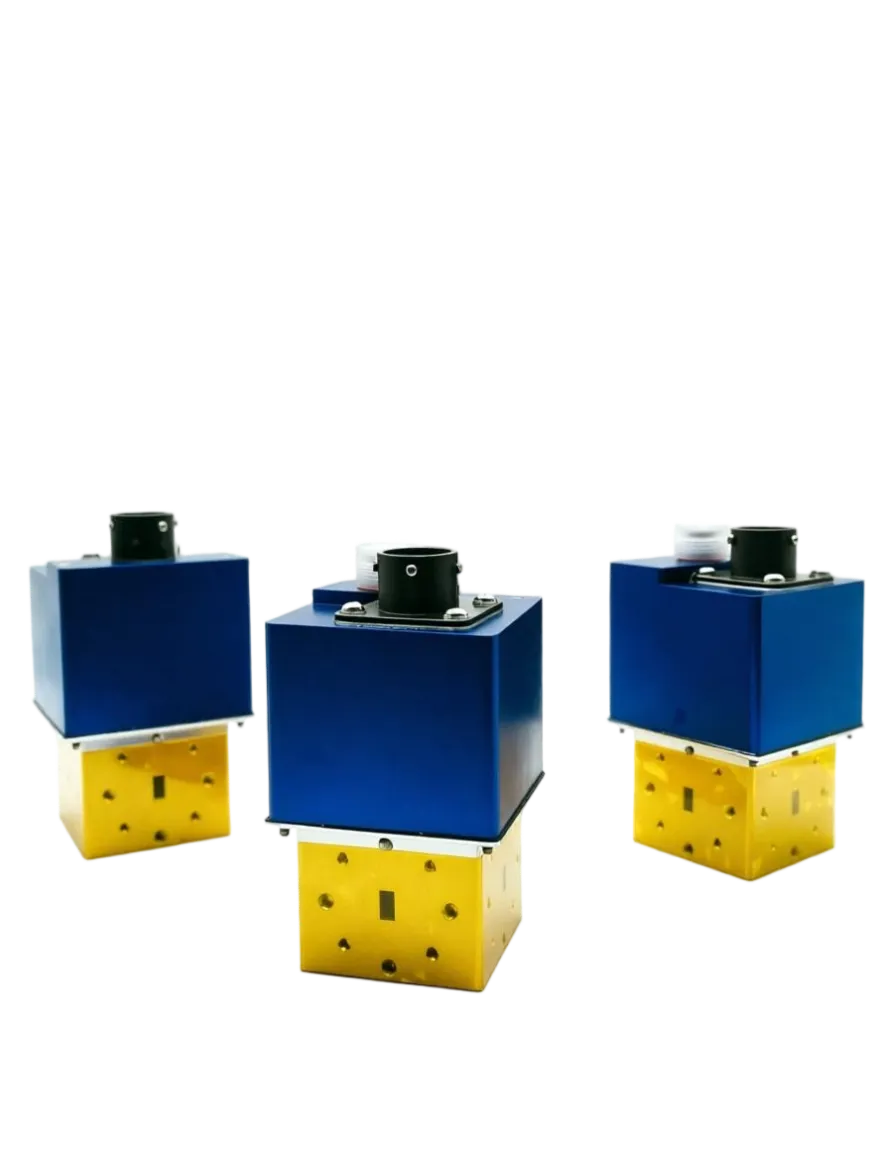
How Do You Keep a Q-Band Link Alive When a Transmitter Fails? Meet the WR22 DPDT Waveguide Switch
Every Q-band system has a bad day waiting for it. A solid-state amplifier drifts out of spec, a traveling wave tube ages, a test bench loses an instrument mid-campaign. The antenna still has to radiate, and the receiver still has to be shielded from whatever the surviving transmitter throws at it. That job belongs to a waveguide switch, the part engineers think about last.
The new WR22 DPDT waveguide switch from AO Microwave covers 30 to 50 GHz with 0.20 dB insertion loss, VSWR 1.20, and 50 dB isolation in a latching transfer configuration. Here is what those numbers buy you in the field.
A switch is really a spare tire, not a component
Nobody specifies a waveguide switch because they enjoy switching things. You specify it because you want an option at the worst possible moment. A gateway with a standby high-power amplifier, a radar with two transmitter chains, a production line running over-the-air tests on millimeter-wave modules: all share one failure mode. Something upstream dies, and a working system is now sitting behind a dead one.
The cost of that moment is rarely the amplifier. It is the outage, the missed campaign window, the engineer driving to a remote site at 3 a.m. A switch that moves the signal path in one command turns a multi-hour outage into a two-minute procedure, and that is the return you are actually buying.
What DPDT gives you that SPDT cannot
An SPDT switch sends one input to either of two outputs. A DPDT transfer switch has two poles and two throws, so it carries four waveguide ports and two signal paths that move together under a single command. Picture a gateway with a main transmitter and a hot standby. The main amplifier feeds the antenna while the standby sits on a load, and one command swaps both paths when the main unit trips. No extra waveguide runs, no second switch to sequence, no chance of an operator getting the order wrong.
Two SPDT switches bolted together can imitate that behavior, and they double the flange count in a run where every joint is another place to leak, corrode, or lose a tenth of a decibel. One transfer switch replaces that stack and holds the mechanical reference rigid, which matters when you need phase repeatability across a calibration path. Where protection matters more than routing, a waveguide isolator does that job instead.
The four numbers that decide your link budget
| Parameter | Specification |
| Frequency range | 30 to 50 GHz |
| Waveguide size | WR-22 (IEC R400, British WG-23, 5.69 x 2.845 mm) |
| Configuration | DPDT transfer, latching, 4 ports |
| Insertion loss | 0.20 dB |
| VSWR | 1.20 (return loss 20.8 dB) |
| Isolation | 50 dB |
| Flange | UG-383/U round cover, standard WR-22 interface |
Insertion loss of 0.20 dB sounds like a rounding error until you convert it. It means 4.5 percent of the power you send in never reaches the other side. Run 100 W continuous through the switch and roughly 4.5 W turns into heat inside the housing, which is why the body needs a real thermal path to the mounting surface rather than a thin bracket. Published datasheets for comparable motorized WR-22 DPDT transfer switches in the same band commonly list 0.4 dB typical insertion loss and 20 dB return loss, so holding 0.20 dB hands margin back to a link already fighting rain fade.
VSWR 1.20 equals 20.8 dB return loss, about 0.8 percent of the incident wave reflecting back toward your amplifier. At 1.25:1 you are at 19.1 dB and 1.2 percent. That difference stops looking slight when the reflected wave has to survive the isolator on the way back to a GaN device that costs more than the switch.
Isolation of 50 dB is the number that protects your receiver. Feed 100 W (50 dBm) in and the isolated port sees roughly 1 mW, or 0 dBm. A low noise amplifier that a watt of leakage would destroy shrugs off a milliwatt. Drop isolation to 30 dB and that same port sees 100 mW, which is enough to end the conversation. A transfer switch gets there through rotor-to-stator tolerances and quarter-wave chokes rather than ferrite material, and the WR-22 core is small enough that those tolerances are measured in microns. Our article on the waveguide circulator covers the non-reciprocal route, and the WR-22 dimensions and flange data are published for anyone checking the interface against existing hardware.
Latching or failsafe: decide what happens when power dies
This is the decision most people make by accident, then live with for years. A latching switch needs a short pulse of control power to move, then stays where it is with no holding current. A failsafe switch returns to a spring-loaded default the moment control power disappears.
Choose latching when the last commanded state should be preserved and when you would rather not dissipate holding current inside an already warm enclosure, which is what this WR22 unit does. Choose failsafe when losing power must produce a known RF path, for example dropping a transmitter onto a dummy load so a receiver stays safe. Position indicators and a manual override knob are worth ordering either way, because the first field fault you debug will probably be a control cable in the wrong socket.
Where a 30 to 50 GHz switch earns its keep
WR-22 is the standard Q-band rectangular waveguide, listed with the UG-383/U round flange in ETSI EN 305 550-1 (2014-10), where Q band is given as 33 to 55 GHz. Traffic in and around that window keeps arriving from several directions:
- 5G millimeter-wave test. 3GPP TS 38.104 places FR2-1 between 24.25 and 52.6 GHz and defines band n260 (37 to 40 GHz) and band n259 (39.5 to 43.5 GHz) inside it. Modules built for those bands get validated on a bench where signals must be routed and muted without touching a flange.
- Satellite gateways and feeder links. The Ericsson Mobility Report (June 2026) reports global mobile network data traffic at 210 exabytes per month in Q1 2026, up 22 percent year on year, and forecasts 515 EB per month by 2031 including fixed wireless access. That growth pushes operators into higher spectrum and more gateway hardware, and Q-band feeder links are where the upgrade lands.
- Radar and electronic warfare. Redundant transmitter chains and calibration paths need a switch that survives vibration and never drifts out of position when a platform loses power.
- Automated test benches. One switch, two devices under test, no recabling between runs. Operators stop wearing out connectors and stop making mistakes at 6 p.m. on a Friday.
Three things to check before you buy any Q-band switch
- Is loss specified at the band edges, and isolation across temperature? A figure quoted only at mid-band or only at 25 °C will not hold at 30 GHz and again at 50 GHz, warm.
- What is the hot-switching limit, and what is the cycle life? Ask before you plan a sequence that throws the switch under full power.
- Does the flange actually mate? The same flange series is not the same thing as aligned dowel pin holes and the right cover depth.
If you are weighing other sizes or actuator options, the waveguide switch family runs from WR-137 down to WR-10 in SPDT and DPDT, latching or failsafe, so the Q-band unit is one point on a ladder rather than a one-off build.
Frequently asked questions about waveguide switches
Q: What does DPDT mean on a waveguide switch, and when do I need it instead of SPDT?
Double pole double throw. It has four waveguide ports and two signal paths that switch together, so one command can move a transmitter chain and a receive chain, or swap a main unit and its standby. Pick DPDT when two paths must change state together, or to avoid stacking two SPDT switches in series. Pick SPDT when only one path needs routing.
Q: Is VSWR 1.20 good for a Q-band switch?
Yes. VSWR 1.20 is a return loss of 20.8 dB, about 0.8 percent reflected power. Comparable motorized WR-22 DPDT switches are commonly published at 20 dB return loss, which is 1.25:1 and 1.2 percent reflected. The tighter figure gives your amplifier more headroom and makes the load presented back through the chain more predictable.
Q: Can I switch while RF power is running through the switch?
Do not. Hot switching means throwing the rotor while high power is live, and as it turns, the gap between ports widens. That gap is where voltage breakdown and arcing happen, and arcing carbonizes the cavity and permanently raises insertion loss. Mute the RF source before you command a change. It costs milliseconds and saves the switch.
Q: Latching or failsafe: which actuator should I order?
Order latching if you want the selected path retained with no holding current and no extra heat, which suits standby transmitters and remote sites. Order failsafe if a loss of control power has to produce a known, repeatable RF state, such as dropping a transmitter into a load to shield a receiver. Both can be supplied with position indicators and a manual override.
Q: How much isolation do I actually need to protect a receiver?
Work backward from your leakage budget. At 50 dB isolation, 100 W at the input appears as roughly 1 mW at the isolated port. At 40 dB it becomes about 10 mW, and at 30 dB it climbs to 100 mW, enough to damage an unprotected low noise amplifier. Add the transmit power and the LNA damage threshold, then compare against the switch rating.
Q: What flange comes with a WR-22 waveguide switch, and will it fit my existing hardware?
WR-22 hardware uses the UG-383/U round cover flange, listed alongside the R400, WG-23, and WR-22 designations in ETSI EN 305 550-1. The interface is standard, but send the mating flange drawing anyway and we will confirm bolt pattern, dowel pin alignment, and cover depth before machining.
Q: How long will a latching waveguide switch last?
Latching switches in this family are rated above one million cycles typical when operated within the specified voltage and environmental limits. The actuator is rarely the first thing to fail; control wiring, connector torque, and dust getting past a sealed actuator cover cause more field problems than the rotor does.
Need to route 30 to 50 GHz without losing your margin?
Tell us your WR size, configuration, control logic, voltage, and flange style. Our engineering team will confirm the interface against your existing run and send a quotation with datasheet within 24 hours.