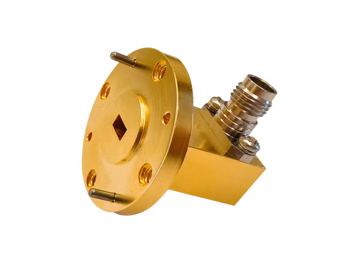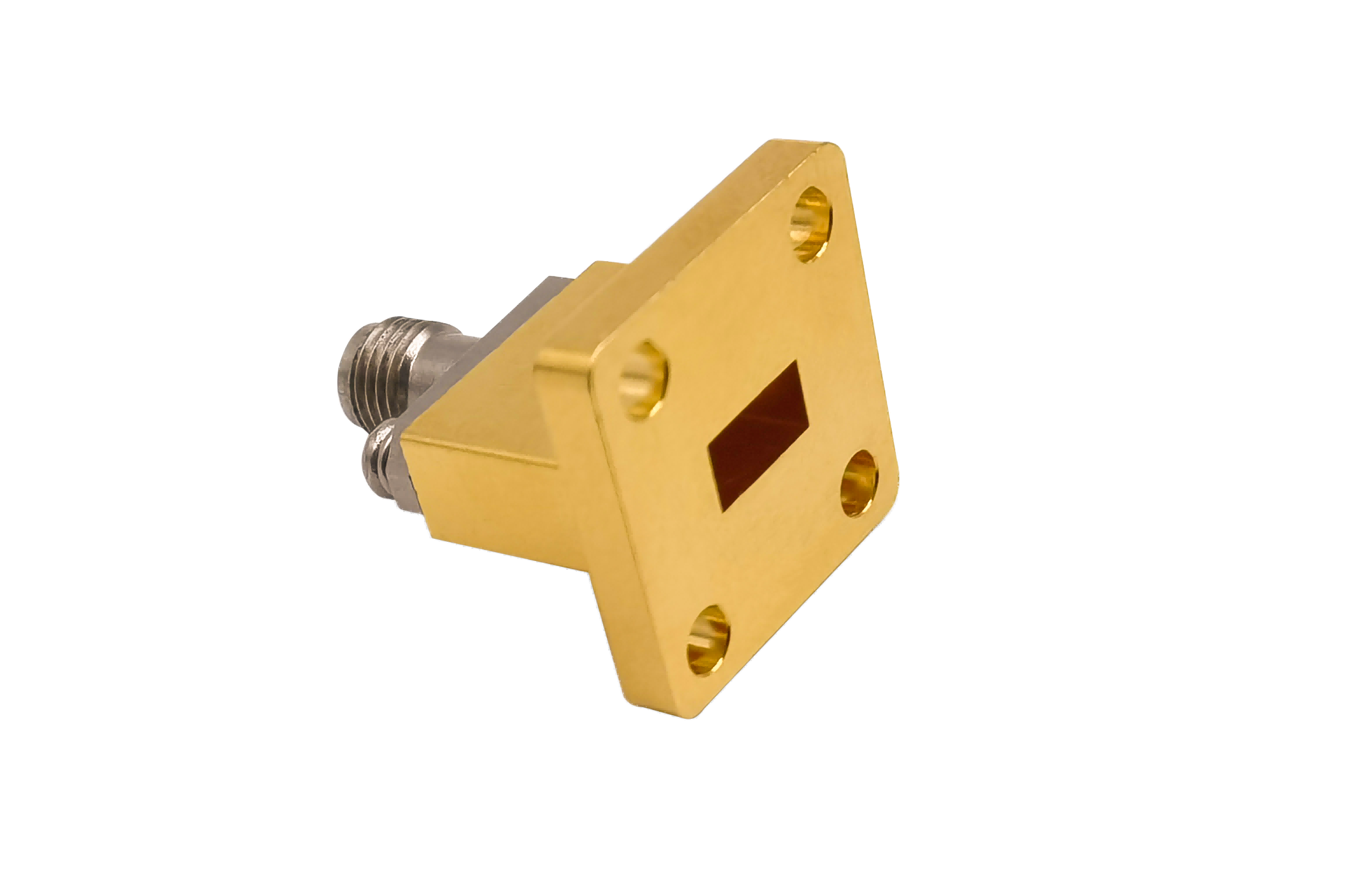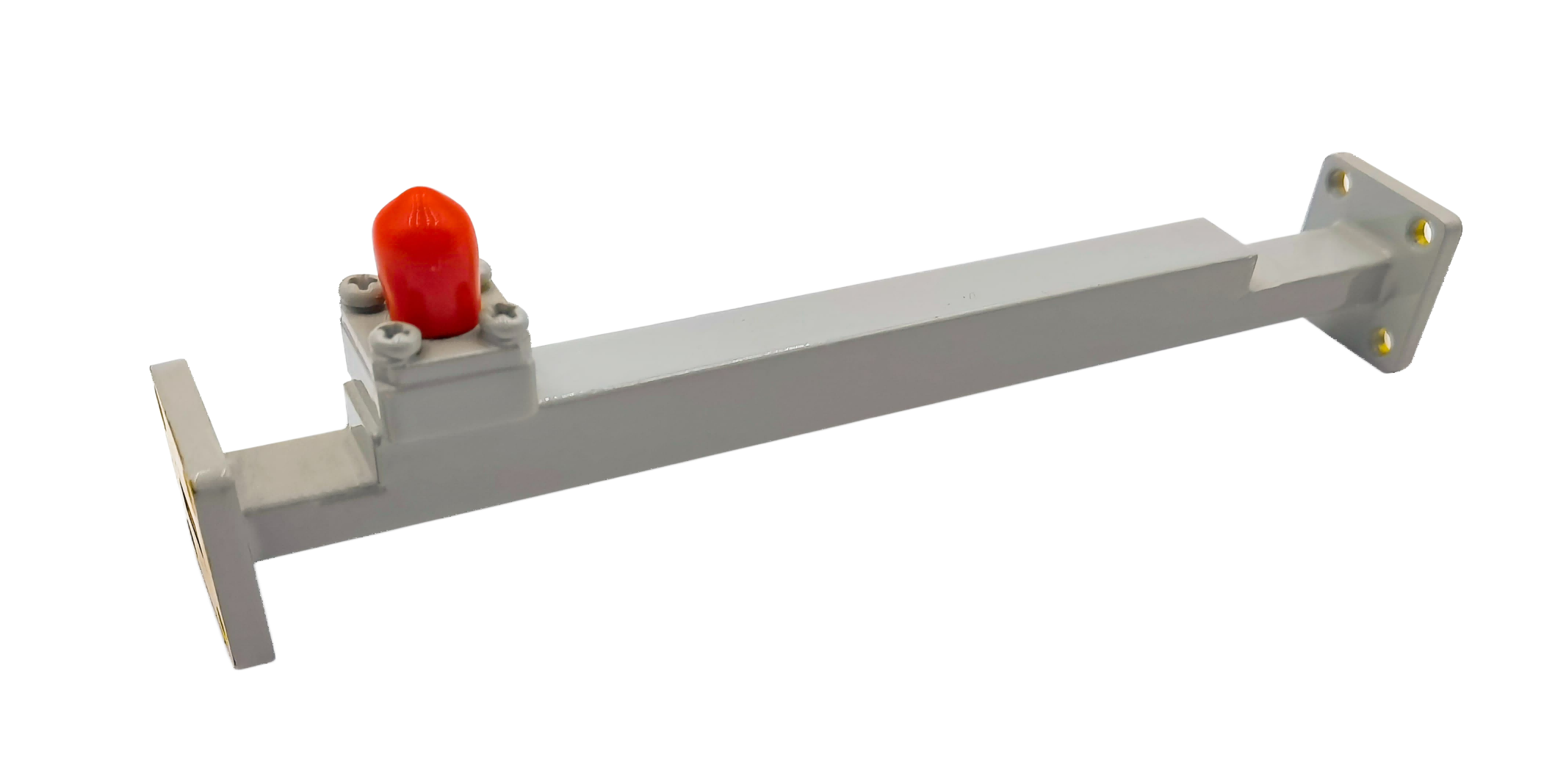
Broadwall Directional Coupler
Broadwall Directional Coupler provides stable microwave signal coupling through the waveguide broad wall. Suitable for radar platforms, satellite communication links, RF monitoring systems and microwave measurement applications.
High-Directivity Broadwall Directional Couplers
AO Microwave’s parallel broadwall directional couplers are designed for ultra-flat power sampling and high-precision signal monitoring along the broad wall of rectangular waveguides. Precision-machined from lightweight aluminum and highly conductive copper alloys, these parallel-line couplers feature silver-plated internal paths and gold-plated contacts to minimize insertion loss on the main transmission line. Working up to 110 GHz, our broadwall couplers utilize multi-aperture array designs to deliver an exceptional directivity of typically > 35 dB to 40 dB and coupling flatness within ±0.5 dB across the full waveguide band.
These parallel couplers distribute coupling apertures in mathematically optimized patterns (such as Chebyshev or binomial distributions) to ensure stable performance. They are vital for precise VSWR measurements, calibration loops, and high-power monitoring in active satellite ground stations and complex military radar transmitter networks.
| Part No | Frequency/GHz | Main VSWR (Max) | Sec VSWR (Max) | IL/dB (Max) | Coupling Optional/dB | Directivity/dB (Min) | Flange Type | Connector Type |
|---|---|---|---|---|---|---|---|---|
| AO975-WCXNKPPACG | 0.75-1.15 | 1.1 | 1.25 | 0.2 | 3~60 | 20~40 | UDR9 | N Female |
| AO770-WCXNKPPACG | 0.96-1.46 | 1.1 | 1.25 | 0.2 | 3~60 | 20~40 | UDR12 | N Female |
| AO650-WCXNKPPACG | 1.13-1.73 | 1.1 | 1.25 | 0.2 | 3~60 | 20~40 | UDR14 | N Female |
| AO510-WCXNKPPACG | 1.45-2.20 | 1.1 | 1.25 | 0.2 | 3~60 | 20~40 | UDR18 | N Female |
| AO430-WCXNKPPACG | 1.72-2.61 | 1.1 | 1.25 | 0.2 | 3~60 | 20~40 | UDR22 | N Female |
| AO340-WCXNKPPACG | 2.17-3.30 | 1.1 | 1.25 | 0.2 | 3~60 | 20~40 | UDR26 | N Female |
| AO284-WCXNKPPACG | 2.60-3.95 | 1.1 | 1.25 | 0.2 | 3~60 | 20~40 | UDR32 | N Female |
| AO229-WCXNKPPACG | 3.22-4.90 | 1.1 | 1.25 | 0.2 | 3~60 | 20~40 | UDR40 | N Female |
| AO187-WCXNKPPACG | 3.94-5.99 | 1.1 | 1.25 | 0.2 | 3~60 | 20~40 | UDR48 | N Female |
| AO159-WCXNKPPACG | 4.64-7.05 | 1.1 | 1.25 | 0.2 | 3~60 | 20~40 | UDR58 | N Female |
| AO137-WCXNKPPCSG | 5.38-8.17 | 1.1 | 1.25 | 0.3 | 3~60 | 20~40 | UDR70 | N Female |
| AO112-WCXNKPPCSG | 6.57-9.99 | 1.1 | 1.25 | 0.3 | 3~60 | 20~40 | UBR84 | N Female |
| AO90-WCXNKPPCSG | 8.20-12.5 | 1.1 | 1.25 | 0.3 | 3~60 | 20~40 | UBR100 | N Female |
| AO75-WCXNKPPCSG | 9.84-15.0 | 1.1 | 1.25 | 0.3 | 3~60 | 20~40 | UBR120 | N Female |
| AO62-WCXSKPPCSG | 11.9-18.0 | 1.1 | 1.25 | 0.3 | 3~60 | 20~40 | UBR140 | SMA Female |
| AO51-WCXSKPPCSG | 14.5-22.0 | 1.1 | 1.25 | 0.3 | 3~60 | 20~40 | UBR180 | SMA Female |
| AO42-WCX2.92KPPCSG | 17.6-26.7 | 1.1 | 1.5 | 0.3 | 3~60 | 20~40 | UBR220 | 2.92mm Female |
| AO34-WCX2.92KPPCSG | 21.7-33.0 | 1.1 | 1.5 | 0.3 | 3~60 | 20~40 | UBR260 | 2.92mm Female |
| AO28-WCX2.92KPPCSG | 26.5-40.0 | 1.1 | 1.5 | 0.3 | 3~60 | 20~40 | UBR320 | 2.92mm Female |
| AO22-WCXPPCG | 33.0-50.0 | 1.1 | 1.25 | 0.5 | 3~60 | 20~40 | UG-383/U | N/A |
| AO19-WCXPPCG | 40.0-60.0 | 1.1 | 1.25 | 0.5 | 3~60 | 20~40 | UG383/UM | N/A |
| AO15-WCXPPCG | 50.0-75.0 | 1.1 | 1.25 | 0.5 | 3~60 | 20~40 | UG385/U | N/A |
| AO12-WCXPPCG | 60.0-90.0 | 1.1 | 1.25 | 0.5 | 3~60 | 20~40 | UG-387/U | N/A |
| AO10-WCXPPCG | 75.0-110.0 | 1.1 | 1.25 | 0.5 | 3~60 | 20~40 | UG387/UM | N/A |
Understanding Parallel Coupling Physics & Chebyshev Distribution
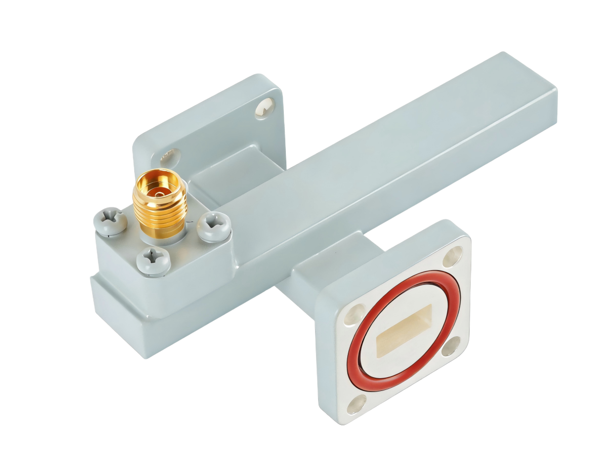
Unlike crossguide couplers where the waveguides cross orthogonally, broadwall couplers position the primary and auxiliary waveguides parallel to one another. Coupling occurs through an array of apertures machined into the common wide wall. To achieve high directivity and flat coupling over the entire operating frequency band, the size and spacing of these holes must be mathematically varied.
AO Microwave designs its broadwall couplers using a multi-hole Chebyshev distribution array. Spaced at precise quarter-wavelength intervals, these apertures allow forward-traveling waves from each hole to add in-phase at the coupled port, while reverse-traveling waves cancel out in the isolated port. Because this design utilizes multiple coupling points, it provides high directivity (typically > 35 dB) and excellent coupling flatness across full waveguide bands, though it requires a longer physical length than crossguide designs.
Key Features & Applications
- Unmatched Directivity (> 35 dB): Essential for high-precision VSWR measurements, allowing the coupler to accurately isolate the reflected wave from the forward wave.
- Bilateral Stability: Symmetrical housing machining and internal termination design provide stable performance across temperature variations.
- Precision Radar Monitoring: Used as primary inline calibration loops for military radar and weather tracking transceivers.
Broadwall Directional Coupler FAQs
Need high-performance Broadwall Directional Couplers?
Specify your WR size, coupling factor (3/10/20/30/40 dB), port layout, and flange style — we'll quote in 24 hours.