
What Is a Waveguide Isolator and Why Is It Important in RF Systems?
Learn how a waveguide isolator works: ferrite gyromagnetic resonance, three construction types, and key specs (isolation, insertion loss) for radar,satcom and 5G.
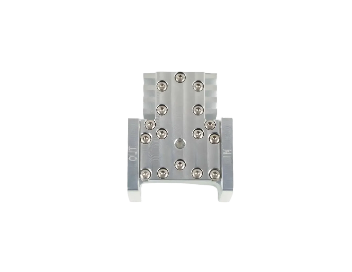
What Is a Waveguide Isolator and Why Is It Important in RF Systems?
Walk into any radar transmitter room or satellite earth station, and you will find waveguide isolators installed between the power amplifier and the antenna feed — not as an optional accessory, but as a non-negotiable line of defense. An isolator is a two-port ferrite device that lets microwave energy flow forward with minimal loss while absorbing anything that tries to come back the other way. In a discipline where one reflected pulse can destroy a traveling-wave tube amplifier (TWTA) costing tens of thousands of dollars, the isolator earns its keep every time the system powers up.
This article explains what makes waveguide isolators work at the physics level, how they differ from circulators, where they fit in real systems, and what specifications drive selection for high-power RF applications.
How a Waveguide Isolator Works: The Ferrite Non-Reciprocity Principle
To understand an isolator, start with a fact most RF engineers take for granted until it bites them: nearly every passive microwave component — couplers, adapters, straight waveguide sections — is reciprocal. A signal traveling from Port A to Port B experiences the same insertion loss, phase shift, and reflection behavior as one traveling from Port B to Port A. Classical electromagnetics offers no mechanism to break this symmetry. Ferrites do.
Gyromagnetic Resonance and One-Way RF
Inside a waveguide isolator sits a slab or puck of ferrite material — a ceramic compound typically made of iron oxide alloyed with nickel, zinc, or yttrium (YIG). Ferrites contain unpaired electrons whose magnetic spins precess when hit by an RF magnetic field, like a spinning top wobbling under gravity. The trick: apply a strong DC magnetic bias from a permanent magnet oriented perpendicular to the RF propagation direction, and suddenly the precession frequency depends on which direction the wave travels (rfessentials.com, Ferrite-Loaded Waveguide).
Forward-traveling waves interact constructively with the electron spin precession. They see a waveguide loaded with a dielectric that happens to have the right impedance. Reverse-traveling waves interact destructively: the rotating RF magnetic field pushes the spins the wrong way, causing massive absorption or phase cancellation. The reverse signal heats the ferrite — and stays there.
This phenomenon, called gyromagnetic resonance or non-reciprocal propagation, is the foundation of every waveguide isolator and circulator ever built. It operates without any switching, control voltage, or active circuitry. The permanent magnet does all the work.
Three Types of Waveguide Isolator Construction
Not all waveguide isolators use the same physical mechanism. Three architectures dominate real-world designs:
| Type | How It Works | Best For |
|---|---|---|
| Resonance Absorption Isolator | A ferrite slab placed in the plane of circular magnetic polarization. Reverse waves match the electron precession frequency exactly, dumping energy as heat into the ferrite. | High-power radar transmitters; magnetron-based systems; any application with kilowatt-level reflected power to dissipate. |
| Faraday Rotation Isolator | A ferrite rod centered in a circular waveguide. A 45° Faraday rotation in the forward direction is canceled by a resistive card oriented at 45°, absorbing only the reverse wave. | High-isolation test-and-measurement setups; precision lab environments; systems where 30 dB+ isolation is non-negotiable. |
| Field Displacement Isolator | A ferrite slab bonded to the waveguide wall shifts the E-field distribution. Forward waves concentrate away from a resistive card; reverse waves concentrate onto it and get absorbed. | Compact systems with space constraints; medium-power SATCOM terminals; integrated RF front-ends. |
Resonance absorption isolators dominate the high-power waveguide market. Their ability to dissipate reflected power in the ferrite body itself — combined with robust ceramic-to-metal bonding — makes them the default choice for radar duplexers and broadcast transmitters.
Isolator vs. Circulator: One Port Makes All the Difference
Every waveguide isolator is, in effect, a three-port waveguide circulator with the third port permanently terminated into a matched waveguide load. The circulator routes incoming signals clockwise — Port 1 to Port 2, Port 2 to Port 3, Port 3 back to Port 1. Connect the transmitter to Port 1, the antenna to Port 2, and a high-power termination to Port 3, and you have a working isolator. Any reflection from the antenna enters Port 2, rotates to Port 3, and gets absorbed — never reaching the amplifier at Port 1.
| Aspect | Waveguide Circulator | Waveguide Isolator |
|---|---|---|
| Port count | 3 (or 4 in dual-junction designs) | 2 (externally accessible) |
| Function | Routes signals sequentially between ports; keeps transmit and receive paths separate | Blocks reflected power from reaching the upstream amplifier |
| Internal termination | None (all ports available to user) | Port 3 permanently terminated with a high-power load |
| Insertion loss | 0.2 – 0.4 dB typical | 0.3 – 0.5 dB (slightly higher due to load coupling) |
| Primary application | Radar duplexers (TR switching) | PA output protection stage |
The fact that an isolator starts life as a circulator creates an often-overlooked advantage: both devices share the same ferrite material, the same magnetic bias circuit, and the same waveguide geometry. A manufacturer that masters circulator design can produce isolators with predictable performance across the full waveguide band. At AO Microwave, our waveguide circulator platform serves as the foundation for our isolator lineup — same insertion loss targets, same power ratings, same standard waveguide flanges.
Key Specifications That Define Performance
When evaluating a waveguide isolator for system integration, four parameters separate the commodity products from the mission-critical components:
| Parameter | Typical Range | What It Means in Practice |
|---|---|---|
| Isolation (dB) | 20 – 30 dB | How much reverse power gets blocked. 20 dB means only 1% of reflections reach the amplifier; 30 dB means 0.1%. Every 3 dB improvement halves the risk to your PA. |
| Insertion Loss (dB) | 0.2 – 0.5 dB | Forward power lost to ferrite absorption and ohmic heating. At 1 kW, 0.5 dB means 109 W turning into heat inside the isolator — that heat must go somewhere. |
| VSWR | ≤ 1.15:1 – 1.25:1 | Impedance match at each port. A VSWR of 1.20:1 means roughly 0.8% of forward power reflects at the isolator input — typically negligible but must be budgeted in cascade analysis. |
| Power Handling | 100 W – 10 kW+ CW | Both forward throughput and reverse dissipation matter. A 1 kW isolator with 20 dB isolation must absorb up to 10 W of continuous reflected power in its internal load. |
For systems operating above C-band, frequency-dependent isolation becomes the dominant concern. At mmWave frequencies (26 GHz and above), ferrite materials exhibit narrower gyromagnetic resonance bandwidths, and achieving consistent 20 dB isolation across a full waveguide band requires precise magnetic field uniformity and tight ferrite-to-waveguide mechanical tolerances.
Why Waveguide Isolators Are Critical in Real RF Systems
Radar Transmitters: Protecting Magnetrons and TWTAs
In pulsed radar systems, the transmitter can output megawatt-level peak power. When the antenna scans across a highly reflective target — or worse, when the rotary joint or feed horn develops a fault — the reflected pulse can travel straight back into the magnetron or TWTA output, causing arcing, cathode damage, or complete tube failure. A waveguide isolator positioned immediately after the amplifier output absorbs that reflected energy before it does harm. In military AESA radars, isolators are integrated behind every transmit/receive module, protecting hundreds of individual solid-state amplifiers simultaneously.
Satellite Communications: Keeping Uplink Chains Stable
Satellite earth stations face a unique challenge: the high-power amplifier (HPA) drives a waveguide run that may span tens of meters, passing through combiners, switches, and waveguide-to-coaxial adapters before reaching the antenna. Each junction introduces a potential impedance mismatch. A single isolator at the HPA output decouples the amplifier from everything downstream, ensuring that the amplifier always sees a well-matched load regardless of what happens at the antenna. In N+1 redundant SATCOM gateways, isolators prevent a faulted HPA in the standby chain from pulling down the active chain through the combiner network.
5G and 6G Base Stations: Signal Purity at mmWave
At millimeter-wave frequencies — 28 GHz, 39 GHz, and the emerging 47 GHz band — power amplifier efficiency is already low (typically 15–25%). Even a modest impedance mismatch creates intermodulation distortion (IMD) products that spill into adjacent channels, degrading error vector magnitude (EVM) and violating 3GPP spectral emission masks. A compact waveguide isolator between the PA and the phased-array beamformer suppresses reverse-traveling reflections, linearizes the PA load, and keeps the base station compliant during full traffic load.
Medical and Scientific: MRI and Particle Accelerators
MRI systems use high-power RF pulses to excite proton spins at Larmor frequencies (typically 64–128 MHz for 1.5T–3T scanners in the VHF band, with emerging 7T scanners pushing toward 300 MHz in the UHF band). While MRI operates below traditional waveguide cutoff, the non-reciprocal protection principle remains identical: ferrite isolators prevent reflected RF energy from destabilizing the transmitter chain — a failure mode that can corrupt image quality or force costly system recalibration. In particle accelerator RF chains, waveguide isolators at S-band (2.856 GHz) and X-band (11.424 GHz) protect klystrons driving accelerating cavities, where reflected power can reach tens of kilowatts during beam trips.
Waveguide Isolator vs. Coaxial vs. Drop-in: Form-Factor Tradeoffs
| Parameter | Waveguide Isolator | Coaxial Isolator | Drop-in Isolator |
|---|---|---|---|
| Frequency range | 1.7 – 110 GHz (waveguide band dependent) | 0.5 – 40 GHz (connector limited) | 0.5 – 50 GHz (substrate dependent) |
| Power handling | 100 W – 10 kW+ CW | 1 W – 500 W CW | 0.1 W – 50 W CW |
| Insertion loss | 0.2 – 0.5 dB (lower at wide waveguide) | 0.3 – 0.8 dB (frequency dependent) | 0.5 – 1.5 dB (substrate losses) |
| Isolation | 20 – 30 dB | 18 – 25 dB | 15 – 22 dB |
| Physical size | Large (dictated by waveguide geometry) | Moderate (SMA/N-type connector footprint) | Smallest (surface-mount or drop-in) |
| Best for | High-power radar, SATCOM, broadcast | Test equipment, telecom base stations, general lab | Phased-array modules, compact integrated assemblies |
The waveguide form factor holds an unambiguous advantage in high-power scenarios where thermal management and low insertion loss dominate the design trade space. A coaxial isolator rated for 500 W continuous wave at X-band costs far more per watt than its waveguide equivalent, while drop-in isolators — essential for phased-array integration — simply cannot survive the peak power levels of a pulsed radar front end.
Market Context: A Growing Imperative
The global market for waveguide isolators and circulators is projected to reach approximately $844.8 million in 2025, with a compound annual growth rate (CAGR) of 5.9% through 2033 (Archive Market Research, 2026). Growth is concentrated in three verticals: defense radar modernization programs, low-earth-orbit (LEO) satellite constellation deployments, and 5G/6G infrastructure build-outs at millimeter-wave frequencies. Each of these application domains places isolators at the exact point where failure is most expensive: between the amplifier and the antenna.
What is changing is not whether systems need isolation — they always have — but the bandwidth, power density, and reliability demands placed on the isolator itself. As GaN solid-state amplifiers push power densities higher and phased-array apertures pack more elements into smaller form factors, isolator manufacturers must deliver higher isolation, lower insertion loss, and better thermal stability in the same — or smaller — mechanical envelope.
FAQ
Q: How does a waveguide isolator physically absorb the reflected power?
The reverse-traveling wave interacts destructively with the biased ferrite's electron spin precession. In a resonance absorption isolator, the ferrite slab itself heats up — the reflected RF energy converts directly to thermal energy within the ceramic. In field displacement designs, a resistive card placed along the waveguide wall absorbs the reverse wave. Either way, the key is that only the reverse wave gets absorbed; the forward wave passes with minimal interaction.
Q: What happens when an isolator fails?
Isolator failure typically manifests as degraded isolation — the device still passes forward power but lets increasing amounts of reflected energy through. Causes include permanent magnet demagnetization from overheating, ferrite cracking from thermal shock, or load termination burnout from sustained high reverse power. In a radar system, this failure mode can cascade into PA failure if not caught during routine VSWR monitoring. Most operators schedule isolator performance verification as part of annual preventive maintenance.
Q: Can I use a circulator as an isolator by adding an external load?
Yes. Connect a matched high-power termination to Port 3 of a three-port circulator and you have a functional isolator. This is standard practice in test labs and some field installations. However, the external termination must be rated for the full reflected power the system might encounter — if the load fails, protection disappears. Integrated isolators with factory-terminated ports eliminate this single point of risk.
Q: Why does insertion loss matter so much in high-power isolators?
Insertion loss converts directly to heat inside the device. At 1 kW forward power, 0.3 dB insertion loss means approximately 67 W of continuous heat generation in the ferrite and waveguide body. At 5 kW, that rises to 335 W — enough to require forced-air or liquid cooling. The lower the insertion loss, the less thermal management infrastructure you need. For space-based SATCOM payloads where conduction is the only cooling path, every 0.1 dB matters.
Q: What waveguide bands are most common for isolator deployments?
S-band (2.6–3.95 GHz), C-band (3.95–5.85 GHz), X-band (8.2–12.4 GHz), and Ku-band (12.4–18 GHz) dominate radar and SATCOM applications. Ka-band (26.5–40 GHz) is growing rapidly due to LEO satellite gateway deployments and 5G mmWave backhaul. At WR-28 (Ka-band) and above, ferrite material performance and magnet miniaturization become the primary engineering constraints.
Q: How do I select the right isolator for a pulsed radar system?
Match the peak power rating (not average) to the transmitter's output, accounting for pulse width and duty cycle. Verify that the isolation specification holds across the full operating temperature range — ferrite magnetization weakens with heat, and isolation can degrade by several dB at elevated temperatures. Confirm that the internal load termination can absorb the worst-case reflected power scenario (full reflection, or VSWR = ∞ at the antenna port) without damage.
Need a Waveguide Isolator for Your System?
AO Microwave designs waveguide isolators from S-band through Ka-band, with isolation to 30 dB and power ratings to 10 kW CW. Standard and custom flange configurations available.
Contact Our Engineering Team →