
Coaxial Fixed Attenuator and Load User Manual: How Do You Avoid Burning Out Your Attenuator?
Coaxial fixed attenuator and load manual: impedance matching, CW vs peak power, IEC 61000-4-3 and MIL-STD-461 demand, derating rules, plus FAQs that prevent burnout.
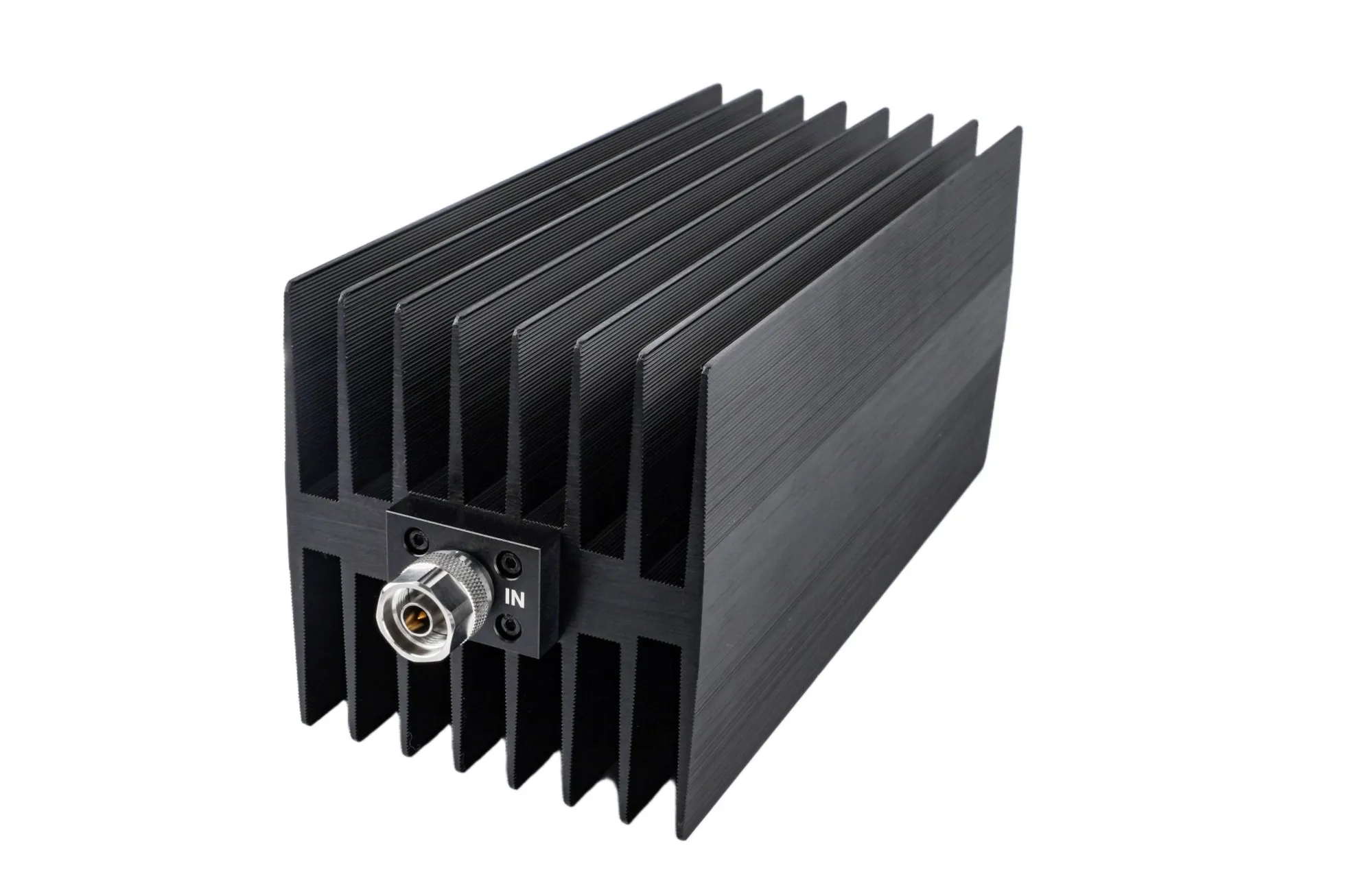
Coaxial Fixed Attenuator and Load User Manual: How Do You Avoid Burning Out Your Attenuator?
Most coaxial fixed attenuator failures do not happen in the field after years of service. They happen in the first hour, on a bench, because of one of four mistakes: the wrong impedance, power applied during connection, continuous power above the rated figure, or a reversed input and output. All four are avoidable once you know what to check.
This manual covers the four areas that decide whether a coaxial attenuator or load survives: impedance, connection order, power handling, interfaces, and derating.
Verify impedance before anything else
Connect a 75 ohm attenuator into a 50 ohm system and the mismatch reflects power back toward your source, where the standing wave raises voltage at the connector and load. The attenuator may survive. The amplifier upstream may not.
Match the ports to the system impedance, normally 50 ohm for test equipment and 75 ohm for broadcast and video. No adapter fixes a genuine mismatch. A 50 to 75 ohm pad is a resistive network with its own loss and VSWR contribution, so it belongs in the chain only where you have allowed for it.
Connection order and the hot-plug rule
Connection sequence matters more than most people expect, because an attenuator connected to a live source can see a transient well above its steady-state rating.
- Power the equipment down.
- Place the attenuator in series, following the direction printed on the body: source to input, output to the receiving device.
- Tighten the connectors to the specified torque. A loose interface adds a return-loss discontinuity exactly where the attenuator is meant to be matched.
- Confirm the source output power before you apply it, so the input cannot exceed the attenuator rating.
- Power up and verify the level at the receiving end.
Do not connect or disconnect an attenuator while the source is transmitting. Coaxial pin geometry makes and breaks the center conductor before the shield in some orientations, the classic route to a damaged element and to electrostatic discharge.
Power handling: continuous wave and peak
Attenuator power ratings are not interchangeable. A CW rating and a peak rating describe different mechanisms, and a part can be safe on one and destroyed by the other.
| Signal type | Rating to check | What it means |
| Continuous wave (CW) | Average power | Steady-state signal. Must not exceed the rated CW figure, for example 10 W. A limit reached in minutes. |
| Pulsed, such as radar | Peak power plus pulse width and duty cycle | A 100 W average rating at 5 microsecond pulse width, with a 1 kW peak at 5 percent duty cycle. The pulse train delivers 50 W of average, so the rating sits higher to absorb material and process variation. Average power heats the element; peak power can break it down. |
For a pulsed source, confirm pulse width, average power, peak power and duty cycle before purchase, and again before use. The figures are not interchangeable: a part can carry 100 W of average power and still break down if the peak far exceeds its pulse rating. If your application is average-power only, the peak figures can be set aside. If it is not, they cannot.
Where does the hardest duty come from? EMC immunity work. IEC 61000-4-3, the radiated radio-frequency electromagnetic field immunity test, defines four levels, 1 V/m, 3 V/m, 10 V/m and 30 V/m, plus an open Level X, all with an 80 percent amplitude-modulated 1 kHz sine carrier. That modulation puts the peak envelope 1.8 times above the unmodulated level, so the amplifier and every pad after it must handle the crest factor, not the average. MIL-STD-461 RS103 goes further: 30 MHz to 18 GHz for all services, 18 to 40 GHz as an option, at 5 to 200 V/m.
Coaxial or waveguide: which attenuator fits your setup?
Most benches run coaxial. A coaxial fixed attenuator mates with SMA, Type N, 2.92 mm or 2.4 mm connectors and covers DC to about 50 GHz with no flange work, while a coaxial load terminates that same line up to 1500 W. The crossover is set by frequency, not by preference. Above roughly 40 GHz the dielectric inside a coaxial line absorbs energy and the connector handles less power, which is where a flange-mounted waveguide load takes over. AO Microwave builds both families, so choose by band edge first, then by power.
Interfaces and connector hygiene
Interfaces must match: SMA to SMA, N to N, 2.92 mm to 2.92 mm. Never force a male into a male or a female into a female, and never mate a 2.92 mm with an SMA and expect the result to hold at the top of the band. They thread together, which is why the damage goes unnoticed until a sweep shows it.
Inspect the mating plane for scratches and check the center pin for recession. A worn interface raises insertion loss and VSWR before it fails outright. Verify attenuation accuracy against the original data rather than the nominal value, so you can see the trend.
Derating, temperature and direction
Three rules cover most of the damage an attenuator takes in service.
- Never exceed the power rating. The resistive element will be destroyed.
- Never reverse the direction. Attenuators carry IN and OUT markings, and the input must go to the source. A higher-power pad is asymmetric: feed the output port and the smaller resistors take the full load and fail fast.
- Watch the case temperature. When it rises, the power you may apply must come down, following the derating curve. Temperature control is not optional on a high-power pad.
If your installation needs ingress protection, ask before you order. It is a build option, not an afterthought.
Quick reference: the numbers that matter
| Parameter | Value or rule |
| System impedance | 50 ohm for test and lab equipment, 75 ohm for broadcast and video. Must match the device under test. |
| CW rating example | 10 W average. A thermal limit reached within minutes, not instantly. |
| Pulsed rating example | 100 W average rating at 5 microsecond pulse width, 1 kW peak, 5 percent duty cycle. The pulse train delivers 50 W average, so the rating sits higher. |
| Temperature drift | Below 0.004 dB per dB per degree C. A 20 dB pad drifting 20 degrees C shifts about 1.6 dB. |
| Recommended headroom | Operate at half the rated power. For 100 W CW, buy the 200 W part. |
Three purchasing rules that double service life
- Size the part at half the power you intend to use. Need to run 100 W CW? Buy the 200 W product. The extra thermal headroom costs far less than the failure it prevents.
- Do not cover a whole band with one high-power pad. A single 18 GHz 100 W part stretched across the range will underperform at the low end. Buy in bands.
- Confirm pulse width, peak power and duty cycle before ordering. If your application is average-power only, you can ignore this. If it is pulsed, it is the whole specification.
Safety warnings
Power down before you touch a connector. An unpowered bench prevents electrostatic discharge from reaching the resistive element.
Never touch the ports while transmitting. RF radiation at these power levels is a health hazard.
Never operate above the rated power. The element fails first and without warning.
The same principle applies further along the chain: a waveguide limiter handles a high-power signal that arrives unannounced, and a waveguide isolator blocks reflected power from reaching the source. Both are worth understanding before you size the attenuator in front of them.
Frequently asked questions about coaxial fixed attenuators and loads
Q: What is the difference between a coaxial attenuator and a waveguide attenuator?
Construction and band. A coaxial attenuator carries the signal on a center conductor inside a dielectric and a shield, mates with SMA, N or 2.92 mm connectors, and covers DC to about 50 GHz. A waveguide attenuator or load passes the wave through a hollow metal guide with no dielectric, mounts by flange, and takes over above roughly 40 GHz where coaxial loss climbs and connector power handling falls.
Q: Can I use a low-power attenuator to measure a high-power signal?
No. The power rating is a thermal limit on the resistive element, and exceeding it destroys the part. To bring a high-power signal down to a level an instrument accepts, use a high-power attenuator or load first, then a second pad. Do not rely on the instrument's protection.
Q: Can I mix 50 ohm and 75 ohm attenuators in one setup?
Only if you accept the mismatch, and normally you should not. A 75 ohm pad in a 50 ohm system reflects power back toward the source, raising the standing wave at the connector and stressing the amplifier upstream. Budget for the extra loss and VSWR first.
Q: Why does reversing a high-power attenuator destroy it?
Because higher-power pads are asymmetric networks. For a 10 dB pad the input stage absorbs about 90 percent of the power and is bonded to the larger heatsink, while the output resistors are much smaller. Feed the output port and those small resistors take the full load and fail within seconds. Low-power pads are symmetrical and can be used either way.
Q: What surface temperature means I need to derate?
Any rise above ambient means you are already in derating territory. Monitor case temperature and follow the derating curve: as surface temperature climbs, the power you may apply must come down. This matters most on loads that absorb full transmitter output.
Q: How do I calculate peak power from average power?
Average power equals peak power multiplied by the duty cycle, so a 1 kW peak at 5 percent duty gives 50 W of theoretical average. A 100 W average rating for that same pulse train is not a contradiction: duty cycle gives the thermal load the signal creates, while the rating sits higher to absorb material and process variation.
Q: Do I need a torque wrench for SMA and N connectors?
Yes, for anything you intend to trust above a few gigahertz. An under-tightened joint adds a return-loss discontinuity exactly where the attenuator is meant to be matched, and it will not show until a sweep does. Over-tightening damages the mating plane and degrades repeatability, so use the torque specified for the connector series.
Not sure which coaxial attenuator rating your application needs?
Send us your frequency range, average and peak power, pulse width and duty cycle. Our engineering team will confirm the attenuator or load, the connector and the derating margin, and quote within 24 hours.