
What Is a Waveguide Limiter and How Does It Protect RF Systems from High-Power Signals?
A waveguide limiter protects RF receivers from high-power signals using a self-biased PIN diode. Learn the working principle, spike vs flat leakage, recovery time, and key WR90 X-band specs.
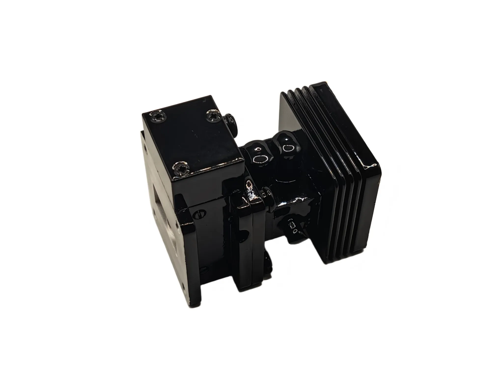
What Is a Waveguide Limiter and How Does It Protect RF Systems from High-Power Signals?
A waveguide limiter is a passive microwave protection device that allows low-power signals to pass through a waveguide transmission line with minimal loss while automatically clamping high-power signals to protect downstream components such as low-noise amplifiers (LNAs), mixers, and detectors. As an RF limiter specialized for the air-dielectric structure of waveguides, it discriminates by power level rather than by frequency.
In a pulsed radar system, the transmitter outputs kilowatts, sometimes megawatts, of peak power through the same antenna that the receiver uses to detect microvolt-level echoes. The circulator or duplexer separates these paths, but no isolation is perfect. A fraction of every transmitted pulse leaks toward the receive chain. Without a waveguide limiter, that leakage reaches the LNA's fragile gate junction and destroys it in nanoseconds. A single failure can cost $2,000–$10,000 in LNA replacement alone and ground an entire system.
What Is a Waveguide Limiter?
A waveguide limiter is a two-port passive device installed in the receive path, immediately ahead of the LNA. Think of it as a circuit breaker for microwave signals: invisible during normal reception, it instantaneously clamps any signal exceeding a defined power threshold.
Unlike an attenuator, which reduces signal power by a fixed amount at all times, a waveguide limiter is power-level-selective. Small signals pass untouched while large ones get clamped. And unlike a filter, which discriminates by frequency, a limiter discriminates by power. The receiver can detect faint echoes without knowing when a high-power pulse will arrive.
Waveguide limiters handle far higher power than coaxial or microstrip equivalents. Their air-dielectric structure sustains kilowatts of peak power without dielectric breakdown, which is why they dominate in radar, EW, and high-power microwave test applications.
Specifying a limiter for a non-standard frequency band? Talk to our engineers →
How Does a Waveguide Limiter Work?
The PIN Diode
Most waveguide limiters rely on a PIN diode, a semiconductor diode with a wide, undoped intrinsic (I) region between p-type and n-type layers. Microwaves101 attributes the power-limiting behavior to this I-layer.
At low signal levels the diode presents high impedance and the insertion loss stays under 0.5 dB. When a high-power pulse arrives, RF energy floods the I-layer with charge carriers, driving impedance sharply downward. The resulting mismatch reflects most incoming power back toward the source, allowing only a controlled leakage to reach the output. Skyworks' PIN limiter design guide describes this same mechanism, noting that the diode acts as an incident-power-controlled variable resistor that reflects rather than dissipates the incident energy.
This is a self-biased (passive) process. The diode rectifies its own bias current from the incident RF pulse and needs no external power. Self-activation, documented in Microwave Journal's coverage of radar receiver protection, works against both the system's own transmitter leakage (synchronous) and external interference (non-synchronous).
Flat Leakage vs. Spike Leakage
Two leakage numbers define a limiter's protective performance, and both must stay below the LNA's damage threshold:
- Spike leakage is the brief energy burst that punches through during the first few nanoseconds, before the PIN diode fully turns on. Measured in ergs, this transient is the leading-edge threat to LNA gate junctions. Per industry references, GaAs LNA damage thresholds fall around 1–10 ergs.
- Flat leakage is the steady-state power that bleeds through once the diode is fully conducting. Measured in milliwatts, it is what the LNA must tolerate for the pulse duration.
Recovery Time
Recovery time is the interval from the end of a high-power pulse to when insertion loss returns to within 1 dB (or 3 dB) of the small-signal value. During recovery the receiver is effectively blinded. Long recovery time matters operationally: per Microwaves & RF, it creates dead zones in radar coverage, especially for short-range targets. Typical values range from hundreds of nanoseconds to microseconds.
Why RF Systems Need a Waveguide Limiter
LNAs, mixers, and detectors are optimized for microvolt-level sensitivity. Their semiconductor junctions cannot survive watt-level inputs. Two failure mechanisms are at play:
- Thermal damage: RF power heats the input transistor until the junction degrades.
- Voltage over-stress: the RF voltage on the gate junction exceeds breakdown.
A degraded but not destroyed LNA can be worse than a dead one. It produces unpredictable behavior and may fail at a critical moment.
During a field deployment of an X-band marine radar, a technician bypassed the limiter during troubleshooting. The next transmitter pulse sent leakage straight into the LNA. The system didn't fail immediately. It ran with 6 dB degraded noise figure for three days before the LNA died. The limiter had been the only thing keeping a marginal design alive.
Threats include own-transmitter leakage (the most common, since waveguide circulator or duplexer isolation is never perfect), external jamming, high-power microwave weapons, and antenna reflections. The limiter sits as the last line of defense, after the circulator or duplexer and before the LNA. See how a waveguide circulator separates TX/RX paths for the upstream protection layer.
Where Waveguide Limiters Are Used
Radar systems (X-band, S-band): The dominant application. In surveillance, weather, marine, and airborne radar, the limiter sits between the duplexer/circulator and the LNA, protecting the receiver from transmitter leakage. The same waveguide chain often includes a waveguide rotary joint for antenna rotation, making system-level integration critical.
Electronic warfare (EW): SIGINT and ELINT receivers face hostile signals designed to overload and blind them. A limiter with low spike leakage and fast recovery is essential for operability under jamming.
An EW integrator once specified a commercial coaxial limiter rated for 50 W peak in a front-end seeing 500 W pulses from a co-located jammer. After three field tests, and three LNA replacements, switching to a high-power limiter rated for 8 kW peak eliminated the failures.
Satellite communication (SATCOM): Ground station receivers, especially X-band telemetry downlinks, face leakage from co-located high-power uplinks. The X-band SATCOM chain shares components with radar, which is why circulators in radar and satellite systems cover closely related protection challenges.
High-power microwave test platforms: When testing amplifiers, spectrum analyzers and network analyzers need protection from unexpected high-power outputs. A limiter on the test bench is insurance against operator error and DUT failures.
Waveguide Limiter vs. Circulator vs. Isolator
These three components are often confused but serve fundamentally different functions, especially in a radar front-end where all three may coexist.
| Aspect | Waveguide Limiter | Waveguide Circulator | Waveguide Isolator |
|---|---|---|---|
| Function | Power-level-selective clamping | Non-reciprocal signal routing between ports | Absorbs reflected power to protect source |
| Ports | 2 (input/output) | 3 (or 4) | 2 (3rd port terminated) |
| Active Element | PIN diode (self-biased) | Ferrite + magnet | Ferrite + magnet + load |
| Protects Against | High-power input to receiver | Separates TX/RX paths | Reflected power from mismatch |
| Power Dependence | Yes — behavior changes with incident power | No — linear passive behavior | No — linear passive behavior |
A circulator routes signals directionally; a limiter clamps power. They are partners, not substitutes. In a radar front-end, the circulator separates TX/RX paths, and the limiter catches whatever leakage gets through. For more depth, read about how a waveguide circulator works.
Key Waveguide Limiter Specifications Explained: WR90 X-Band Example
For context, the AO Microwave AO90-WLTPPC-400W-8.7-9.2 is a WR90 X-band high-power waveguide limiter. Here is what its spec sheet tells you:
| Parameter | Value |
|---|---|
| Frequency Range | 8.7–9.2 GHz (X-band) |
| Waveguide Type | WR90 |
| Flange | FBP100 (Cover) / UBR100 |
| VSWR (Max) | 1.40 |
| Insertion Loss (Max) | 0.80 dB |
| Average Power | 200 W (CW), 400 W (10s) |
| Peak Power | 8 kW |
| Flat Leakage | 20 mW |
| Spike Leakage | 100 mW |
| Recovery Time | 1 µs |
| Impedance | 50 Ω |
| Material | Copper, silver-plated interior, anticorrosion black paint exterior |
| Operating Temp | −40°C to +70°C |
The three numbers that matter most are flat leakage (20 mW), spike leakage (100 mW), and recovery time (1 µs). Both leakage values must stay below the LNA's damage threshold. At 20 mW flat, this design is safe for modern X-band LNAs. Recovery time of 1 µs minimizes radar blind-zone duration, and the 8 kW peak rating confirms it is a genuine high-power limiter, not a test-bench component.
Not sure if these specs match your LNA's damage threshold? Request a custom configuration →
Choosing a Waveguide Limiter: Why Custom Capability Matters
When selecting a waveguide limiter, match these parameters to your system:
- Frequency band — must align with your operating frequency
- Peak and average power — must exceed your worst-case input
- Leakage thresholds — must be below your LNA's damage rating
- Recovery time — must fit your pulse repetition interval
- Waveguide size and flange — must match your waveguide E-bend, waveguide H-bend, flexible seamless waveguide, and waveguide rotary joint runs
- Environmental range — must meet field deployment conditions
Standard off-the-shelf limiters cover common bands, but radar and EW programs frequently need non-standard frequencies or enhanced power handling. That requires a manufacturer who can design the PIN diode stage, waveguide cavity, and thermal path together. AO Microwave designs and manufactures custom high-power waveguide limiters alongside its circulator, bend, and rotary joint lines, which is why custom waveguide manufacturing capability matters at this tier.
And do not overlook the waveguide run itself. Routing errors in bends and flexible sections can degrade limiter performance before the signal even arrives. Our guide to common waveguide routing problems covers those pitfalls in detail.
Frequently Asked Questions
Q: What is a waveguide limiter?
A: A waveguide limiter is a passive two-port microwave protection device that allows low-power signals to pass with minimal insertion loss while automatically attenuating high-power signals to protect sensitive receiver components like LNAs, mixers, and detectors.
Q: How does a waveguide limiter differ from a circulator?
A: A circulator routes signals directionally between ports (non-reciprocal routing); a limiter clamps signal power based on level. In radar front-ends they work together: the circulator separates TX/RX paths, and the limiter catches any high-power leakage reaching the receive chain.
Q: What is the difference between spike leakage and flat leakage?
A: Spike leakage is the brief energy burst in the first few nanoseconds before the PIN diode fully conducts, and it is the leading-edge threat to LNA gate junctions. Flat leakage is the steady-state power that bleeds through once the diode is fully on.
Q: What is recovery time in a waveguide limiter?
A: Recovery time is the interval from the end of a high-power pulse to when insertion loss returns to within 1 dB (or 3 dB) of the small-signal value. During recovery, the receiver is temporarily desensitized.
Q: What power levels can a waveguide limiter handle?
A: Waveguide limiters can handle peak powers from hundreds of watts to several megawatts and average powers from a few watts to hundreds of watts CW. The WR90 example in this article handles 8 kW peak and 200 W CW.
Q: Can I get a custom waveguide limiter for a non-standard frequency?
A: Yes. Because very few manufacturers globally produce waveguide limiters, custom designs for non-standard bands, flanges, or power levels are common. Contact AO Microwave to discuss your requirements.
Conclusion
Specifying a waveguide limiter comes down to three numbers: flat leakage, spike leakage, and recovery time. Get those below your LNA's thresholds and your receiver stays alive. For non-standard frequencies or enhanced power handling where off-the-shelf limiters fall short, request a custom configuration from a manufacturer who can design the full front-end chain.
Designing a Front-End That Has to Survive a High-Power Pulse?
AO Microwave supplies custom high-power waveguide limiters alongside circulators, rotary joints, and precision bends. Share your frequency, average/peak power, and recovery-time targets. Engineering typically responds within one business day.
Contact AO Microwave