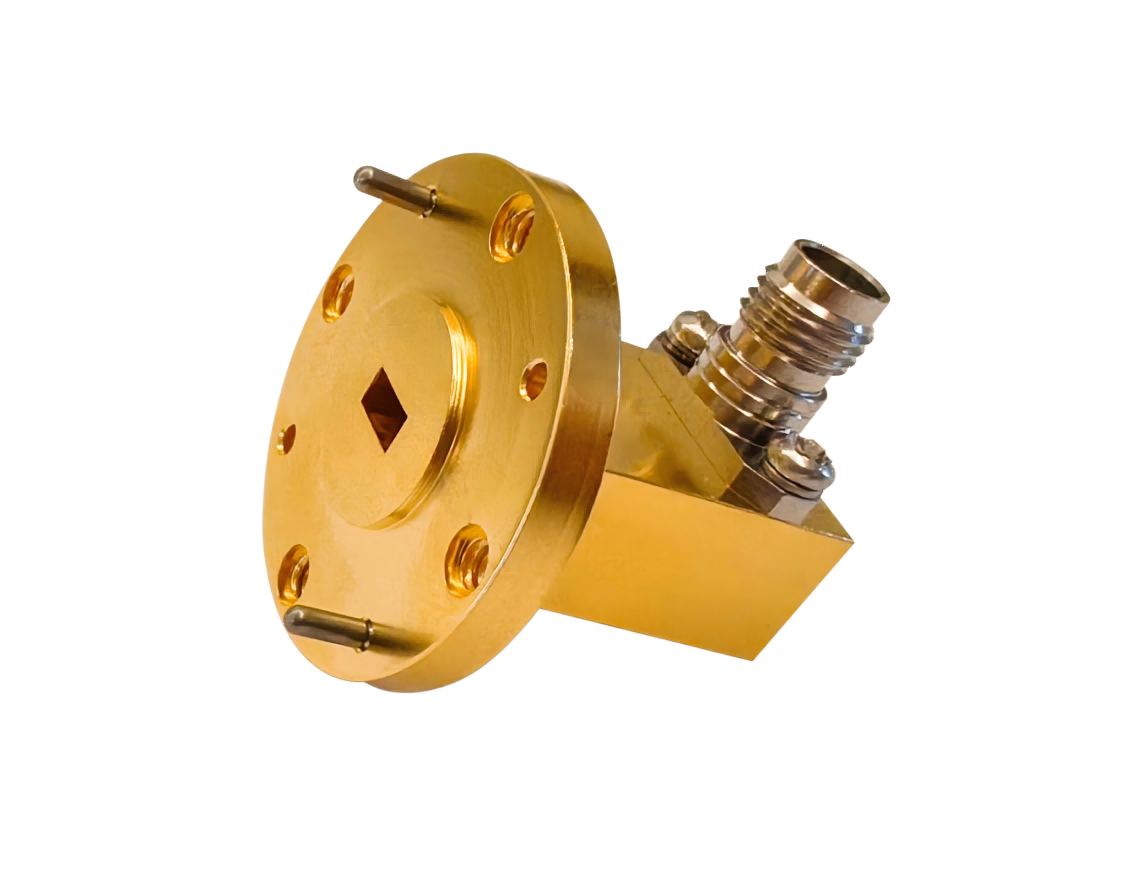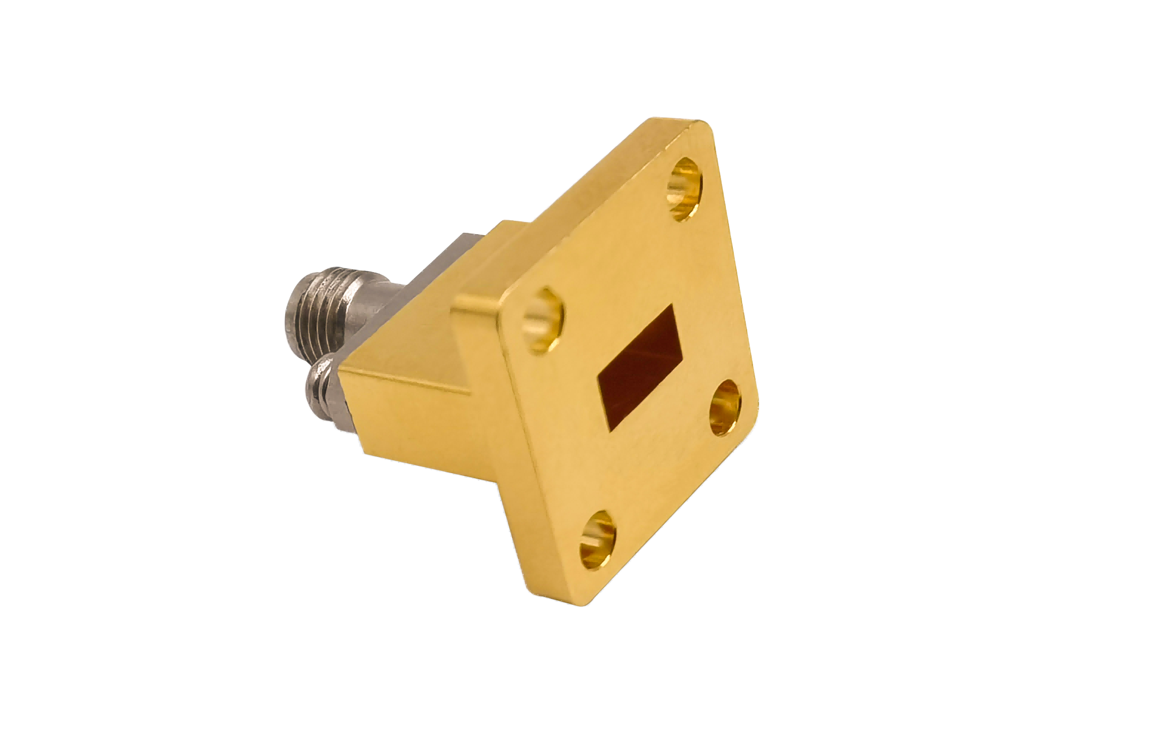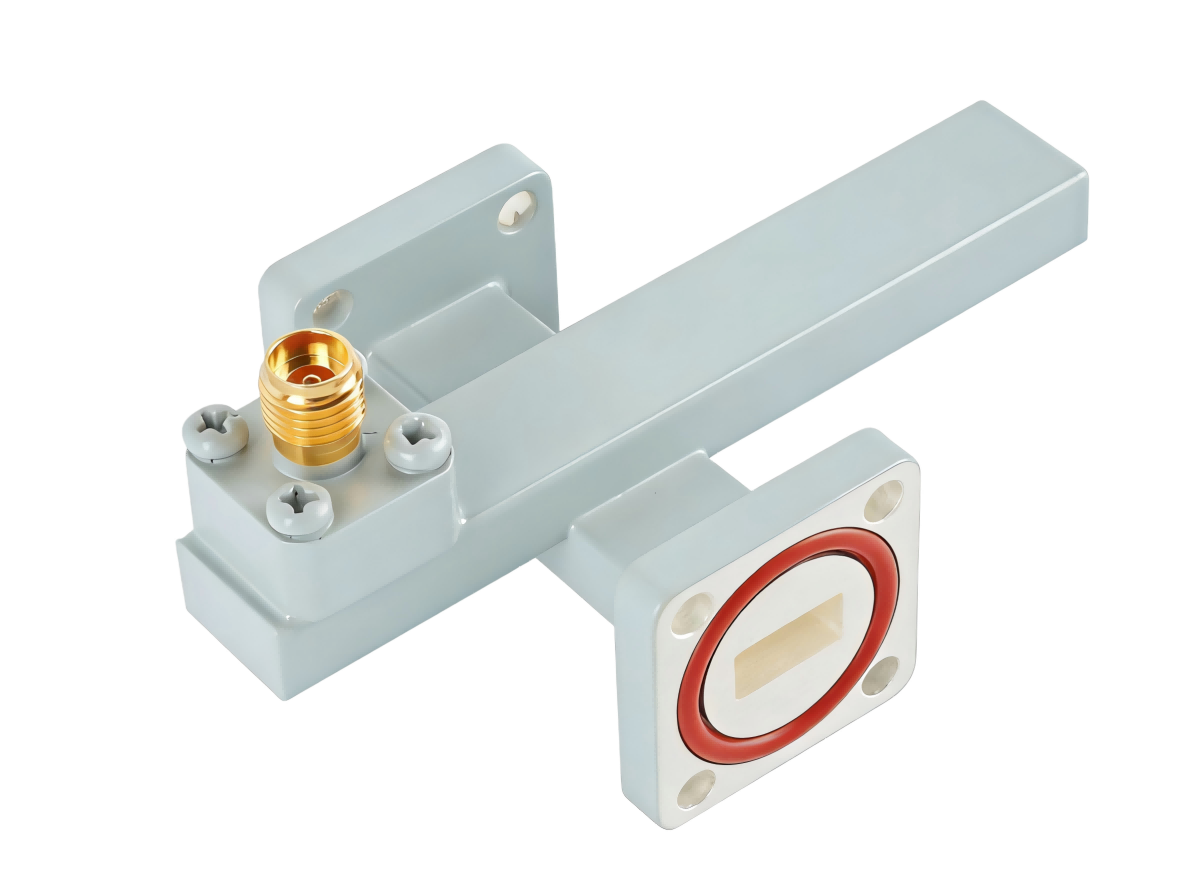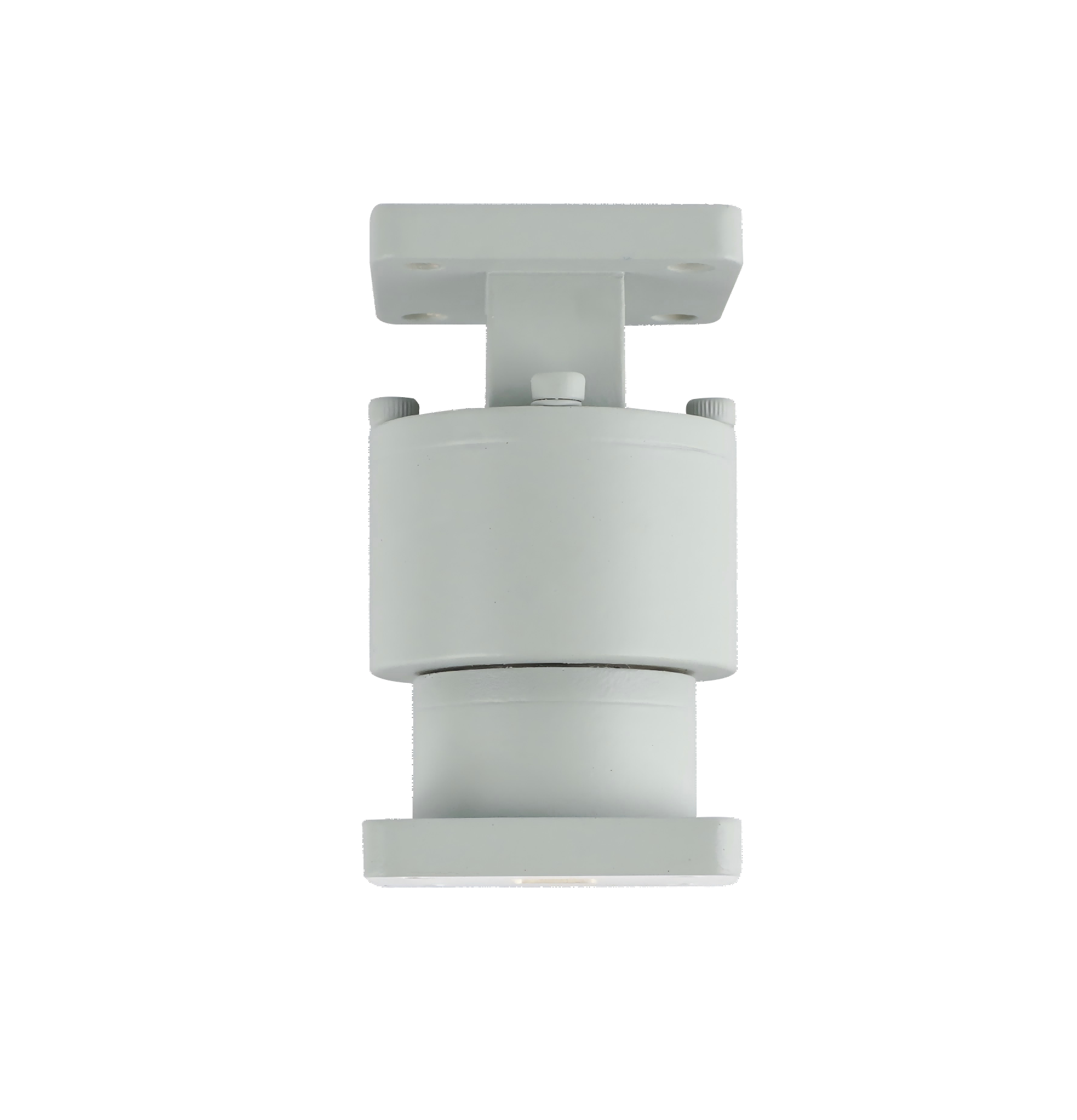
Waveguide Rotary Joint
Waveguide Rotary Joint enables continuous RF signal transmission between stationary and rotating structures. Widely used in rotating radar antennas, satellite tracking systems, microwave communication platforms and aerospace radar systems.
| Part No | Frequency/GHz | Bandwidth | VSWR (Max) | IL/dB (Max) | Average Power/W (Max) | Peak Power/KW (Max) | Style | Flange Type |
|---|---|---|---|---|---|---|---|---|
| AO284-WRJPPACG | 2.60-3.95 | 0.1 | 1.2 | 0.25 | 600 | 600 | I/L/U | UDR32 |
| AO229-WRJPPACG | 3.22-4.90 | 0.1 | 1.2 | 0.25 | 600 | 600 | I/L/U | UDR40 |
| AO187-WRJPPACG | 3.94-5.99 | 0.1 | 1.2 | 0.25 | 600 | 600 | I/L/U | UDR48 |
| AO159-WRJPPACG | 4.64-7.05 | 0.1 | 1.2 | 0.25 | 500 | 150 | I/L/U | UDR58 |
| AO137-WRJPPCSG | 5.38-8.17 | 0.1 | 1.2 | 0.25 | 500 | 150 | I/L/U | UDR70 |
| AO112-WRJPPCSG | 6.57-9.99 | 0.1 | 1.2 | 0.3 | 400 | 150 | I/L/U | UBR84 |
| AO90-WRJPPCSG | 8.20-12.5 | 0.1 | 1.2 | 0.3 | 400 | 150 | I/L/U | UBR100 |
| AO75-WRJPPCSG | 9.84-15.0 | 0.1 | 1.2 | 0.3 | 200 | 10 | I/L/U | UBR120 |
| AO62-WRJPPCSG | 11.9-18.0 | 0.1 | 1.2 | 0.3 | 100 | 4 | I/L/U | UBR140 |
| AO51-WRJPPCSG | 14.5-22.0 | 0.1 | 1.2 | 0.3 | 100 | 3 | I/L/U | UBR180 |
| AO42-WRJPPCSG | 17.6-26.7 | 0.1 | 1.25 | 0.5 | 50 | 0.5 | I/L/U | UBR220 |
| AO34-WRJPPCSG | 21.7-33.0 | 0.1 | 1.25 | 0.5 | 30 | 0.3 | I/L/U | UBR260 |
| AO28-WRJPPCSG | 26.5-40.0 | 0.1 | 1.25 | 0.5 | 30 | 0.3 | I/L/U | UBR320 |
Choke-Type Design for Non-Contact Rotational Coupling
Waveguide rotary joints must transmit high-frequency signals across a rotating interface. In contact-type rotary joints, mechanical friction can lead to physical wear, which increases the insertion loss variation over time.
To resolve these wear-related issues, AO Microwave utilizes a non-contact choke design. By integrating a circular waveguide section operating in the symmetrical TM01 mode, we decouple the physical orientation of the input and output waveguides. Circular choke grooves machined at the rotating interface reflect a short-circuit, preventing RF leakage across the rotational gap. This non-contact coupling ensures a long mechanical lifespan and low insertion loss variation ("Wow") across 360 degrees of rotation.
Target Applications & Operational Advantages
By providing low insertion loss variation and high mechanical durability, our waveguide rotary joints enable stable performance in active tracking systems:
Rotating Radar Pedestals
Function: Transmits high-power radar pulses from the stationary deck up to the continuously rotating scanner antenna.
Advantage: Exceptionally low VSWR and insertion loss variation ("Wow" < 0.05 dB) ensure stable signal detection at all scanning angles.
COTM Tracking Platforms
Function: Bridges RF channels across continuously panning and tilting satellite tracking axes on vehicles or marine vessels.
Advantage: Dual-channel rotary joints allow simultaneous transmit and receive signal paths in a compact, concentric mechanical profile.
Military Fire-Control Trackers
Function: Routes RF signals through complex pan-tilt gimbals for real-time target locking.
Advantage: Low mechanical torque requirements and high-grade bearing structures ensure rapid, drag-free target tracking.
Waveguide Rotary Joint FAQs
Need high-durability Waveguide Rotary Joints?
Specify your WR size, channel configuration, rotational speed (RPM), and flange style — we'll quote in 24 hours.