
Custom Waveguide E-Bend & H-Bend Manufacturer
Looking for a custom waveguide bend manufacturer? Get the complete RFQ checklist, spec guide, and manufacturing process for E-bends and H-bends from AO Microwave.
Custom Waveguide E-Bend & H-Bend Manufacturer
The right custom waveguide bend manufacturer turns your spec sheet into a tested, ship-ready component. Get it wrong, and you are looking at weeks of rework. A non-standard bend angle for a tight payload envelope, a legacy flange type that catalogs no longer stock — these are the jobs where custom fabrication is not a luxury but a necessity.
We cover the parameters you can customize, when custom beats catalog, how to write a spec that eliminates back-and-forth, and what happens on our shop floor between your RFQ and your shipment.
Key Takeaways
- Every waveguide bend parameter, from WR size and bend angle to flange type and surface plating, can be customized. Each choice affects lead time and cost.
- Custom bends become the practical choice when standard catalogs cannot meet your mechanical envelope, flange compatibility, or electrical performance requirements.
- A complete RFQ should include WR size, bend type (E or H), bend angle, material, flange standard, surface finish, and target VSWR.
- Manufacturing custom bends involves engineering review, precision forming or CNC machining, surface treatment, and RF testing before shipment.
- Common ordering mistakes — underspecified flanges, omitted plating requirements, unrealistic VSWR targets — are avoidable with proper preparation.
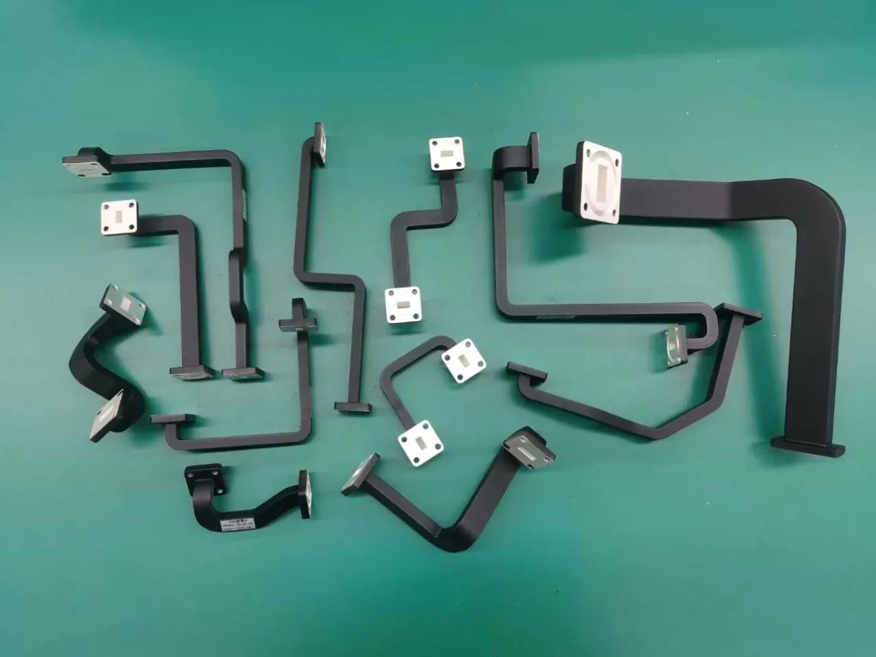
What You Can Customize in a Waveguide Bend
Off-the-shelf waveguide bends cover the usual configurations: WR-90 at 90°, CPRG flanges, copper. When your system needs something different, most parameters can be tailored. A waveguide e bend manufacturer or waveguide h bend manufacturer can adjust the following:
WR size and frequency range. Standard catalogs typically stock the most popular sizes (WR-90, WR-62, WR-28). If your system operates at a less common band — say WR-42 for 18–26.5 GHz or WR-22 for 33–50 GHz — you may need a custom order, as defined by the IEEE standard for rectangular waveguide dimensions and tolerances. At WR-22 and above, a few microns of deviation can push VSWR outside spec. That is where an experienced custom waveguide bend supplier earns its premium. Refer to our waveguide tube size and frequency reference for a full size-to-frequency mapping.
Bend type and angle. The two fundamental geometries are the E-bend (bending along the narrow wall, parallel to the electric field) and the H-bend (bending along the wide wall, parallel to the magnetic field). Standard bends ship at 90 degrees, but 30°, 45°, 60°, and custom angles are all manufacturable. For guidance on which bend geometry fits your routing constraints, see our waveguide bend selection guide. You can also browse specific products on our waveguide E-bend and waveguide H-bend pages.
Material. Copper is the default for its conductivity, but aluminum is common where weight matters, and brass finds use in specialty applications. Material choice affects both RF performance and manufacturability.
Flange type. CPRG, CMR, UG-style, cover, and choke flanges each serve different sealing and alignment needs. Specifying the wrong flange is one of the fastest ways to create a compatibility problem at installation. Our waveguide flange standards and interfaces page covers the major standards and their mechanical interfaces.
Surface finish and plating. Bare copper oxidizes over time, degrading surface conductivity — especially at millimeter-wave frequencies. Silver plating is the most common protective treatment for high-frequency waveguide bends, though gold is used in harsh-environment applications. Surface roughness above 0.4 µm can increase conductor loss significantly in mmWave bands, a phenomenon supported by peer-reviewed research on surface roughness effects in waveguide propagation. For a deeper look at why this matters, see our article on precision manufacturing for millimeter-wave waveguide bends.
VSWR and insertion loss targets. Standard waveguide bends typically specify VSWR below 1.10:1 and insertion loss under 0.1 dB. Instrumentation-grade components push VSWR below 1.05:1 and insertion loss under 0.03 dB, as seen in specifications from manufacturers like Pasternack and Eravant. If your application demands tighter performance, state it explicitly. For a deeper understanding of how VSWR and return loss relate to impedance matching, Rohde & Schwarz provides an excellent technical primer. Use our VSWR vs. return loss reference table to translate between the two metrics when writing your spec.
Want to explore how these options apply to your specific system? Reach out to our engineering team with your requirements and we will help you identify the right configuration.
Custom vs. Standard Waveguide Bends: When Custom Makes Sense
Standard bends have short lead times — typically one to three weeks — and lower unit costs than working with a custom waveguide bend manufacturer. A catalog WR-75 90-degree bend might ship for around $50; see our standard E-bend catalog for current pricing. Custom fabrication, by contrast, can run ten to twelve weeks and cost three to five times the catalog price once tooling and setup are factored in. So when does custom justify the premium?
| Factor | Standard Bend | Custom Bend |
| Lead Time | 1–3 weeks | 6–12 weeks |
| Unit Cost | ~$50 (WR-75 90°) | 3–5× catalog price |
| WR Sizes | Popular only | Any size |
| Bend Angles | 90° standard | Any angle |
| Flange Types | Current production | Any standard or legacy |
| VSWR Guarantee | Typical lot specs | Per-unit testing available |
Mechanical envelope constraints. A satellite communications integrator was designing a Ka-band transceiver that needed a WR-28 E-bend at 45 degrees to route signal around a structural rib in the payload housing. No 45-degree WR-28 E-bend existed in any standard catalog. A custom bend was the only path forward — and the cost of not finding one would have been a mechanical redesign of the entire payload shelf. For similar cases, our analysis of common waveguide routing problems that cause signal loss is worth reading.
Legacy flange compatibility. A radar modernization program needed WR-90 H-bends with UG-39/U flanges to mate with existing waveguide runs installed decades ago. Current production had shifted to CPRG flanges. Custom fabrication preserved the legacy interface without requiring a full flange-adapter chain (and the additional VSWR budget each adapter consumes).
Tighter electrical performance. Some test-and-measurement setups require instrumentation-grade VSWR below 1.05:1 across the full band. Standard bends do not always guarantee that level of performance lot-to-lot. Custom manufacturing with enhanced QC and individual RF testing delivers the repeatability these applications demand.
How to Specify a Custom Waveguide Bend (RFQ Checklist)
A clean specification shortens lead time and cuts back-and-forth. These are the parameters every custom waveguide bend fabrication order should specify:
- Waveguide size (WR designation) — e.g., WR-28, WR-42, WR-90
- Bend type — E-plane or H-plane (see our bend selection guide if you are still deciding)
- Bend angle — 30°, 45°, 60°, 90°, or custom
- Bend radius — minimum or target radius; a radius greater than two wavelengths at the operating frequency keeps reflections to a minimum
- Material — copper, aluminum, brass, or other
- Flange type and standard — CPRG, CMR, UG, cover, choke; include flange orientation if critical
- Surface finish / plating — bare, silver-plated, gold-plated; specify roughness if applicable
- Electrical requirements — target VSWR and insertion loss across the operating band
- Operating frequency range — confirms the correct WR size and validates electrical targets
- Quantity and delivery schedule — affects pricing tiers and production planning
Here is how a complete specification might look in a table format:
| Parameter | Example Spec |
| WR Size | WR-28 |
| Bend Type | E-plane |
| Bend Angle | 45° |
| Bend Radius | ≥ 0.5 in. (min) |
| Material | Copper |
| Flange | UG-599/U (both ends) |
| Plating | Silver (5 µm min) |
| VSWR | < 1.10:1, 26.5–40 GHz |
| Insertion Loss | < 0.1 dB |
| Quantity | 50 units |
Ready to send your spec? Submit your RFQ for a prompt engineering review.
How a Custom Waveguide Bend Manufacturer Builds Your Component
After your specification clears engineering review, production follows a defined sequence. Here is what happens on our floor:
1. Engineering review. The spec is evaluated for manufacturability. If a requested bend radius is too tight for the given WR size, it risks deformation or excessive VSWR. The engineering team will flag it and propose an alternative before production starts. This step prevents costly mid-run corrections.
2. Material procurement. Raw waveguide tube is sourced in the specified material and WR size. For uncommon sizes, procurement lead time may add to the overall schedule. At AO Microwave, we maintain stock of frequently used WR sizes to keep turnaround competitive.
3. Precision forming and CNC machining. The bend is formed to the specified angle and radius. Depending on the geometry, this may involve precision bending, CNC milling from solid block, or a combination. Tight-tolerance features like flange interfaces and critical inner-dimension surfaces are finished to the required tolerances.
4. Surface treatment and plating. After forming, the component is cleaned, prepared, and plated according to spec. Silver plating thickness, adhesion, and uniformity are verified against the order requirements.
5. Quality control and RF testing. Dimensions are checked against the drawing. VSWR and insertion loss are measured across the operating frequency band using calibrated network analyzers. Test data is documented and shipped with the order.
6. Packaging and shipping. Components are packed to prevent flange damage and surface contamination during transit. Custom packaging is available for sensitive or high-value orders.
This same process applies across our waveguide product line, including straight waveguide sections and flexible seamless waveguide, ensuring consistent quality regardless of geometry.
Common Mistakes When Ordering Custom Waveguide Bends
After reviewing countless OEM waveguide bend specifications, a few recurring errors stand out. Avoiding them saves time and money:
1. Omitting the flange standard. "WR-90 90° E-bend" is not a complete specification. Without the flange type (CPRG? UG-39/U? Cover?), the manufacturer cannot guarantee mechanical compatibility with your existing waveguide run. Always specify both the flange standard and its orientation on each end.
2. Requesting an unrealistically tight bend radius. A bend radius below two wavelengths at the operating frequency invites elevated VSWR and insertion loss. If the mechanical envelope demands a tighter radius, a miter bend may be a better option — but that is a different component with different trade-offs. For more on how underspecified geometry creates system-level problems, see our article on manufacturing tolerances for high-frequency bends.
3. Forgetting to specify plating. An unplated copper bend may perform well in a lab, but in a humid or corrosive environment, surface oxidation will degrade performance over time. State your plating requirement upfront — it affects both cost and lead time.
4. VSWR targets without a frequency range. Stating "VSWR < 1.05:1" without specifying the bandwidth means the manufacturer cannot design or verify to your actual operating condition. Always pair electrical targets with the frequency range over which they must be met.
5. Ordering one unit for a custom configuration. The tooling and setup costs for a custom bend are largely fixed regardless of quantity. Ordering a single unit may cost nearly as much as ordering five, because the engineering review, programming, and first-article inspection are the same. If you anticipate future need, consider ordering a small batch to amortize the setup cost.
Custom Waveguide Bend Manufacturer: Frequently Asked Questions
Q: What is the typical lead time for custom waveguide bends?
Standard waveguide bends typically ship in one to three weeks. Custom bends generally require six to twelve weeks, depending on the complexity of the specification, material availability, and current production capacity. Providing a complete and accurate specification at the outset is the single most effective way to avoid delays.
Q: Can I order bends with non-standard WR sizes?
Yes. While standard WR designations (e.g., WR-28, WR-42, WR-90) are the most common, we can manufacture bends to non-standard internal dimensions when the application calls for it. Be prepared to provide the precise inside dimensions and the operating frequency range.
Q: What is the minimum order quantity for custom bends?
There is no strict minimum order quantity, but due to the fixed costs of engineering review, tooling, and first-article inspection, the per-unit cost for very small quantities will be significantly higher. We are happy to quote single-unit and low-volume orders so you can evaluate the cost-benefit trade-off.
Q: Do you provide VSWR test data with custom orders?
Yes. Every custom waveguide bend is RF-tested across the specified operating frequency band before shipment, and test data is documented and provided with the delivery. For applications requiring even more rigorous verification, we can arrange for individual serialized test reports with swept-frequency measurements.
Choosing the right custom waveguide bend manufacturer means your E-bends and H-bends arrive tested, documented, and ready to install — whether you need a non-standard bend angle, a legacy flange type, or instrumentation-grade VSWR. Use the RFQ checklist above to prepare a complete specification, and reach out to discuss your requirements.
Need a Custom Waveguide Bend Manufacturer to Build to Your Spec?
From non-standard WR sizes to legacy flange compatibility, our engineering team will review your requirements and deliver tested, ship-ready components.
Contact Our Engineering Team