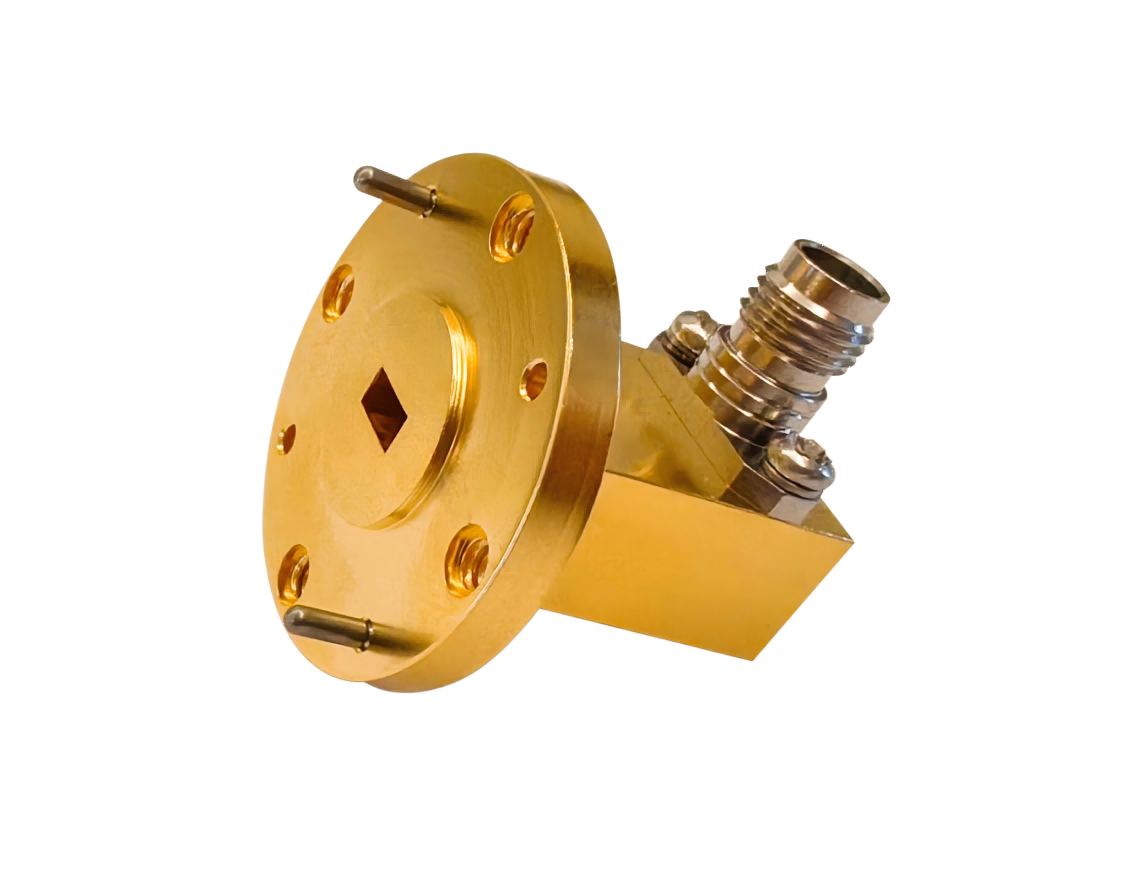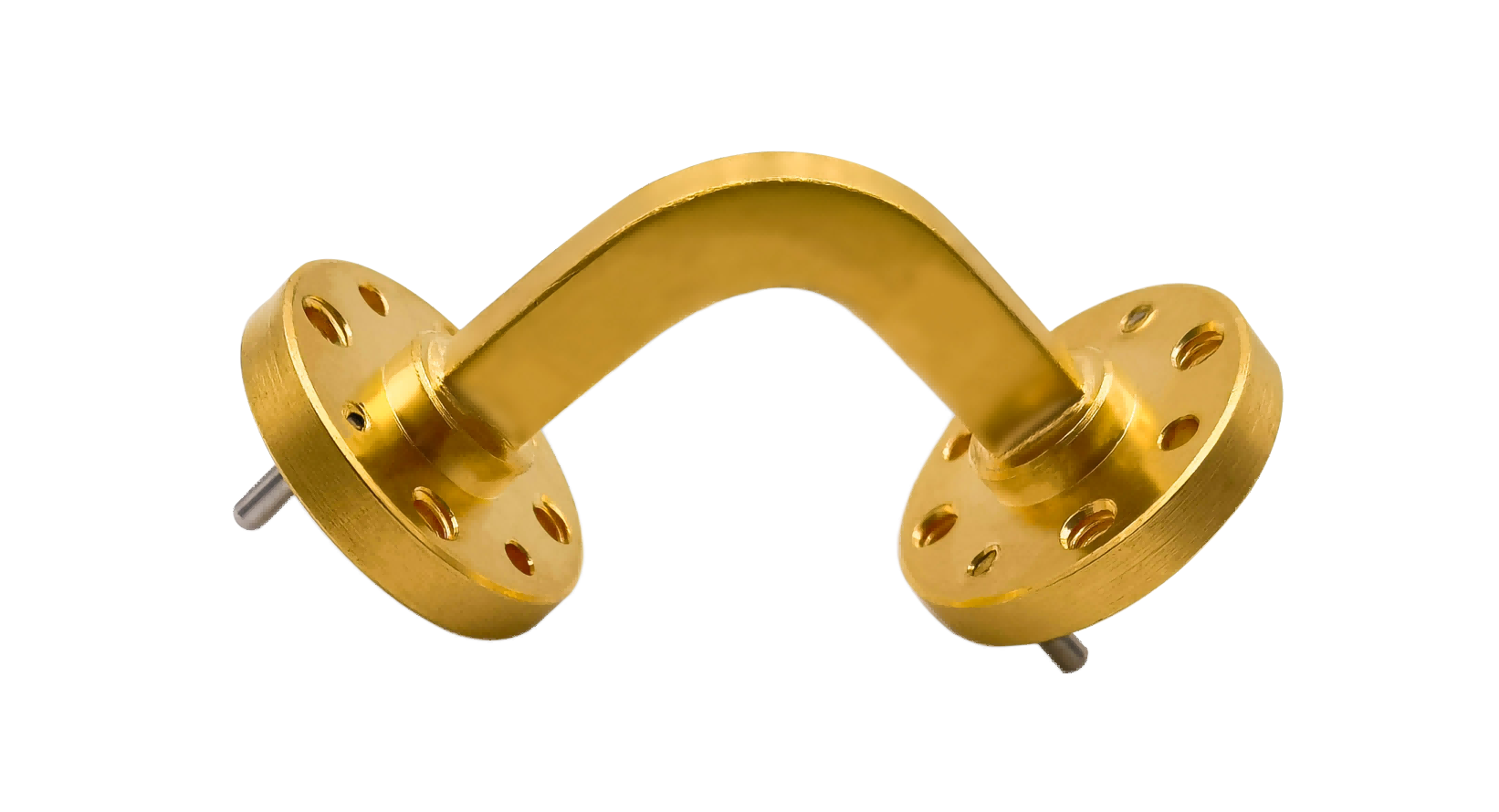
Waveguide H-Bend
Waveguide H-Bend enables smooth microwave signal routing in the H-plane with minimal reflection and insertion loss. Suitable for radar systems, satellite ground stations, microwave communication equipment and millimeter-wave RF applications.
Premium Waveguide H-Bends for High-Performance Horizontal Routing
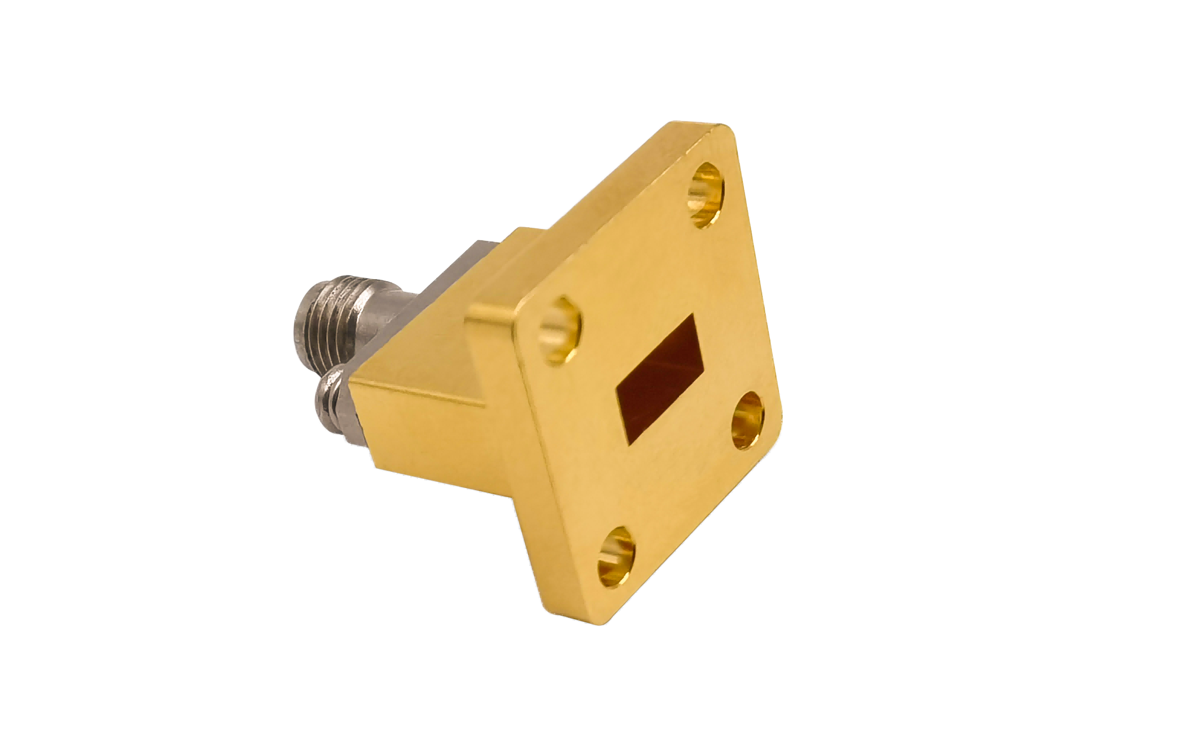
AO Microwave's waveguide H-bends (Magnetic-plane bends) are designed to redirect electromagnetic signals smoothly along the broad wall of rectangular waveguides. Supporting standard sizes up to 110 GHz, our H-bends deliver broad operating bandwidths, keeping VSWR < 1.10:1 across the full waveguide band while minimizing signal insertion loss. Machined to high geometric tolerances, these horizontal bends allow clean integration in compact system plumbing, satellite transceivers, and complex laboratory test benches.
To withstand harsh field environments while maintaining excellent electrical conductivity, our H-bends are produced using high-quality alloy metals and stable plating options:
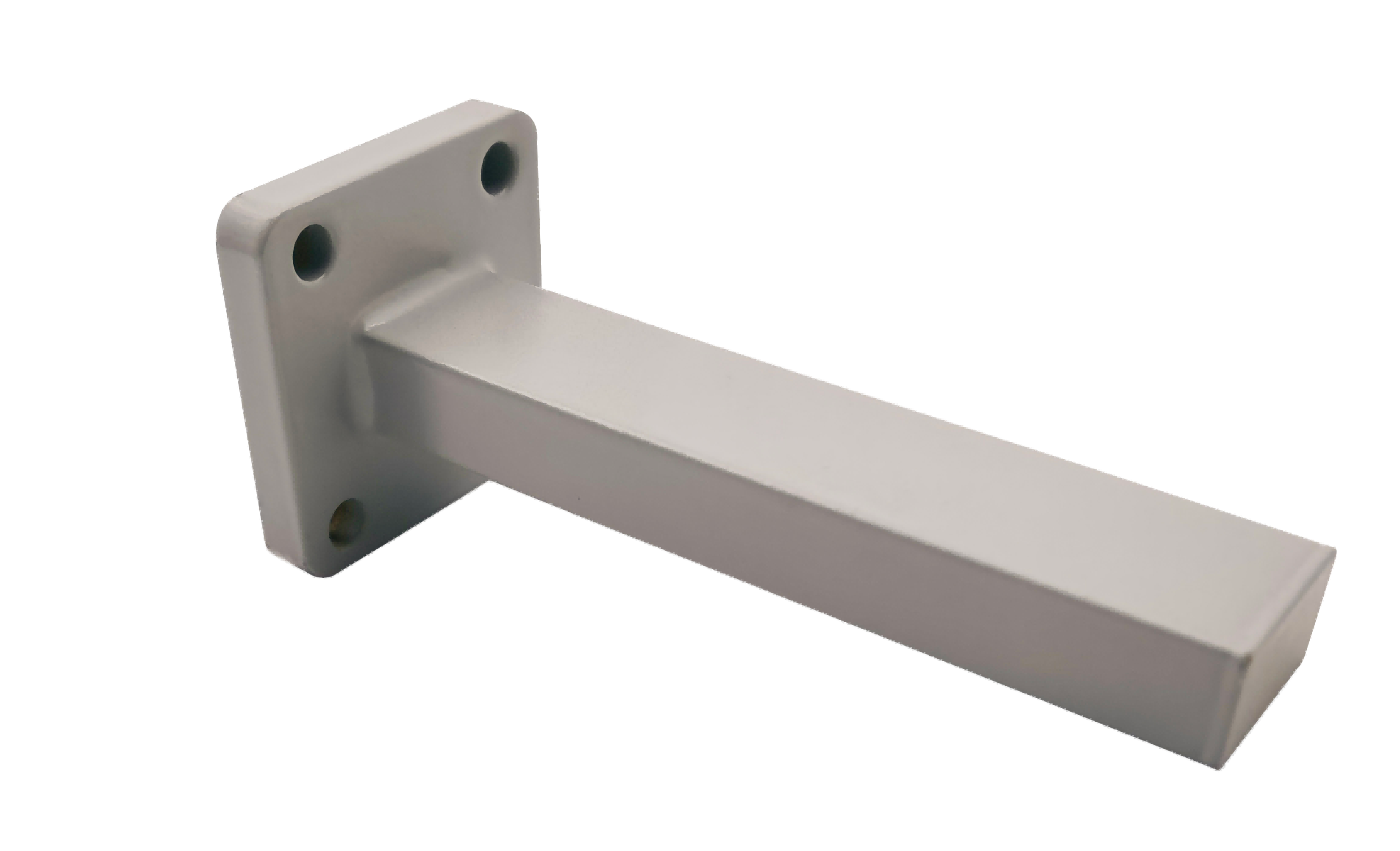
- Aluminum: Excellent mechanical integrity with minimal weight, making it highly suitable for structural satellite and defense components.
- Copper: Provides maximum electrical conductivity and low thermal resistance, suitable for continuous high-power microwave systems.
- Stainless Steel: Offered in specialized cryogenic and thermal isolation laboratory setups to prevent environmental temperature drift.
- Advanced Finishes: High-purity silver plating for minimized skin-depth losses, gold plating for contact preservation, chromate passivation, and weather-proof epoxy coatings.
| Part No | Frequency/GHz | VSWR (Max) | IL/dB (Max) | Standard Length/mm | Flange Type |
|---|---|---|---|---|---|
| AO430-WHBAXBPPACG | 1.72-2.61 | 1.1 | 0.2 | A=150 B=150 | UDR22 |
| AO340-WHBAXBPPACG | 2.17-3.30 | 1.1 | 0.2 | A=180 B=180 | UDR26 |
| AO284-WHBAXBPPACG | 2.60-3.95 | 1.1 | 0.2 | A=150 B=150 | UDR32 |
| AO229-WHBAXBPPACG | 3.22-4.90 | 1.1 | 0.2 | A=80 B=80 | UDR40 |
| AO187-WHBAXBPPACG | 3.94-5.99 | 1.1 | 0.2 | A=80 B=80 | UDR48 |
| AO159-WHBAXBPPACG | 4.64-7.05 | 1.1 | 0.2 | A=80 B=80 | UDR58 |
| AO137-WHBAXBPPCSG | 5.38-8.17 | 1.1 | 0.3 | A=70 B=70 | UDR70 |
| AO112-WHBAXBPPCSG | 6.57-9.99 | 1.1 | 0.3 | A=70 B=70 | UBR84 |
| AO90-WHBAXBPPCSG | 8.20-12.5 | 1.1 | 0.3 | A=50 B=50 | UBR100 |
| AO75-WHBAXBPPCSG | 9.84-15.0 | 1.1 | 0.3 | A=40 B=40 | UBR120 |
| AO62-WHBAXBPPCSG | 11.9-18.0 | 1.1 | 0.3 | A=40 B=40 | UBR140 |
| AO51-WHBAXBPPCSG | 14.5-22.0 | 1.1 | 0.3 | A=30 B=30 | UBR180 |
| AO42-WHBAXBPPCSG | 17.6-26.7 | 1.1 | 0.3 | A=30 B=30 | UBR220 |
| AO34-WHBAXBPPCSG | 21.7-33.0 | 1.1 | 0.3 | A=30 B=30 | UBR260 |
| AO28-WHBAXBPPCSG | 26.5-40.0 | 1.1 | 0.3 | A=30 B=30 | UBR320 |
| AO22-WHBAXBPPCG | 33.0-50.0 | 1.15 | 0.5 | A=25 B=25 | UG-383/U |
| AO19-WHBAXBPPCG | 40.0-60.0 | 1.15 | 0.5 | A=25 B=25 | UG383/UM |
| AO15-WHBAXBPPCG | 50.0-75.0 | 1.15 | 0.5 | A=25 B=25 | UG385/U |
| AO12-WHBAXBPPCG | 60.0-90.0 | 1.15 | 0.5 | A=25 B=25 | UG-387/U |
| AO10-WHBAXBPPCG | 75.0-110.0 | 1.15 | 0.5 | A=25 B=25 | UG387/UM |
Waveguide H-Bend Engineering Considerations
H-bends guide electromagnetic propagation along the wide wall of rectangular waveguides (H-plane). Because this bend geometry spans the larger physical dimension of the waveguide, designers must plan for specific spatial and current-flow characteristics:
1. Managing the Physical Spatial Envelope
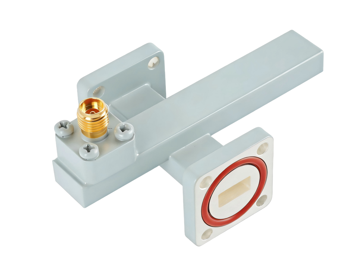
Bending along the wider dimension naturally requires a larger physical bend radius to avoid damaging the waveguide tube. If your design faces strict layout limitations, Mitered H-bends offer an ultra-compact alternative. They utilize a precision internal chamfer to execute sharp 90-degree corners, keeping the footprint to an absolute minimum.
2. Optimizing Broadwall Current Flow
In rectangular waveguides operating in the TE10 mode, longitudinal RF wall currents flow primarily along the center of the wide walls. Since H-bends sweep this wide wall, internal surface roughness or physical stretching directly interrupts this current flow, which can increase insertion loss.
Overcoming Critical H-Bend Design Challenges
We address key challenges often raised by engineers in RF engineering forums when implementing horizontal routing:
The Space-Envelope Crunch in Dense Waveguide Systems
Standard sweep H-bends require significant installation space. To overcome this spatial bottleneck, AO Microwave utilizes precision split-block CNC EDM machining to produce high-performance Mitered H-bends. This specialized technique delivers compact horizontal transitions with dimensional tolerances controlled to ±0.02 mm, allowing stable electrical behavior in dense microwave manifolds.
Minimizing Insertion Loss in Millimeter-Wave Bands
At high frequencies, surface roughness acts as a series of physical obstructions that increase RF attenuation due to the skin effect. To prevent this, we utilize precision internal mandrel processes and chemical polishing. This results in highly polished internal waveguide walls that minimize conductor loss and keep attenuation values to near-theoretical minimums.
Where Waveguide H-Bends are Deployed
Our precision horizontal bends are key components in dense microwave layouts where coaxial cables introduce excessive signal loss:
- Satellite Up/Downconverter Systems: Ruggedized, low-insertion-loss horizontal routings used in Ka-band, Ku-band, and Q/V-band installations.
- High-Power Military Radars: Durable waveguide H-bends capable of sustaining high peak and average power levels without mechanical failure or degradation.
- VNA Calibration & Measurement Laboratories: Precision bend components engineered to provide highly repeatable phase and amplitude references during testing.
Waveguide H-Bend FAQs
Need custom Waveguide H-Bends for your layout?
Specify your WR size, bend radius or mitered spec, flange type, and quantity — we'll quote in 24 hours.