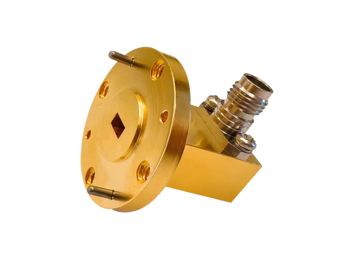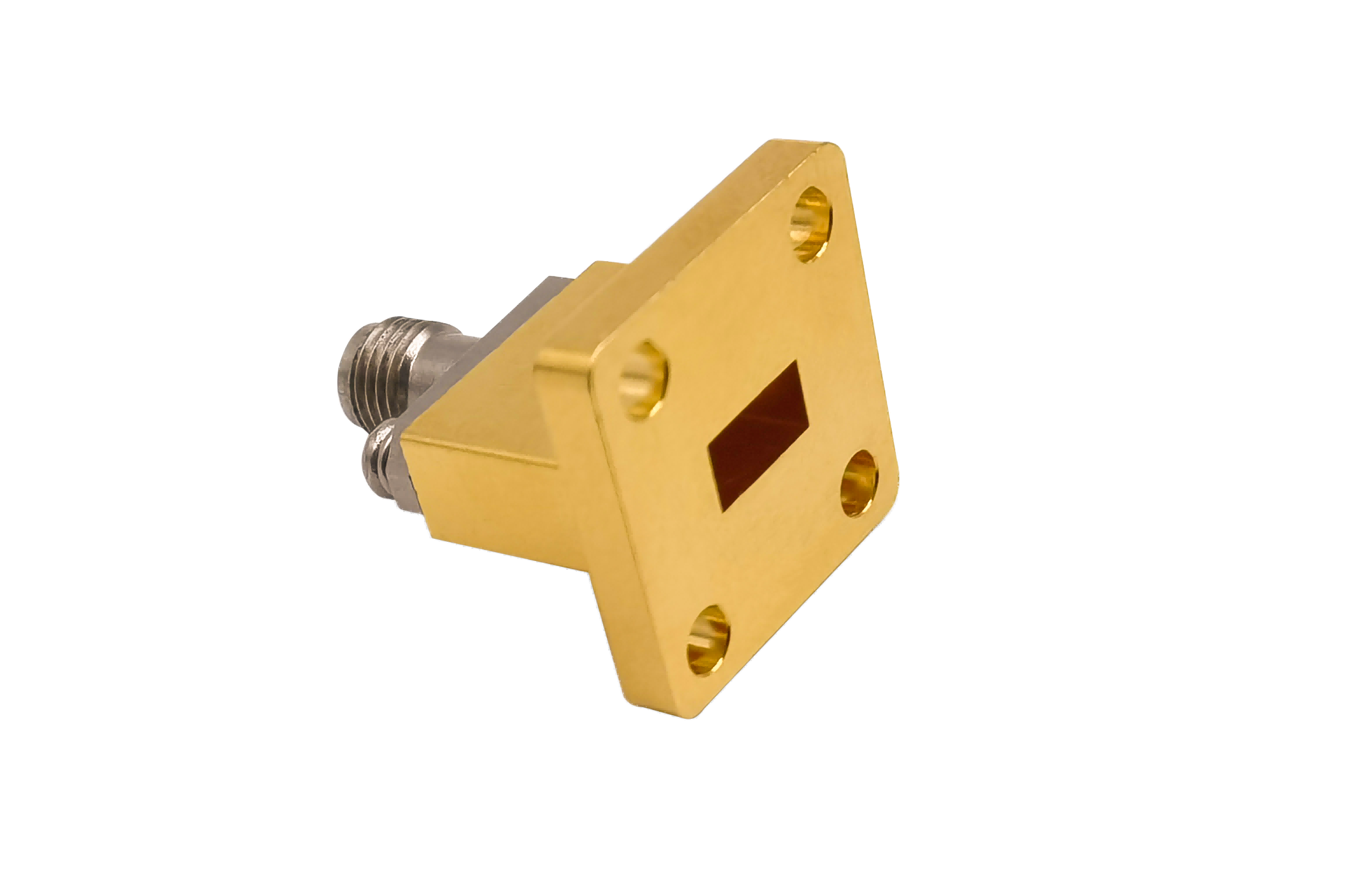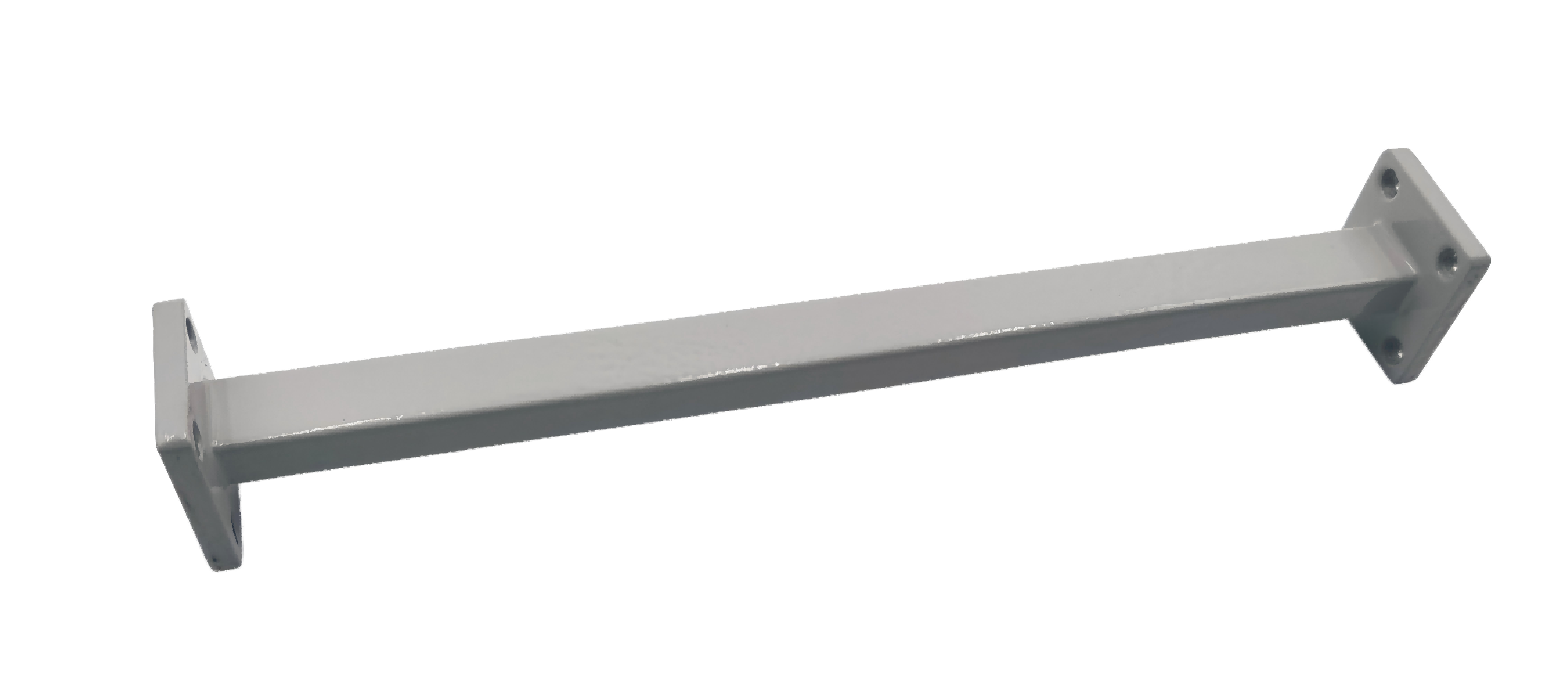
Straight Waveguide
Straight Waveguide sections designed for low-loss microwave and millimeter-wave signal transmission. Manufactured with high precision for stable RF performance in radar systems, satellite communication, aerospace, defense electronics, RF test systems and 5G/mmWave applications.
High-Performance Straight Waveguides for Millimeter-Wave Systems
AO Microwave's straight waveguide sections are engineered to deliver low-loss and stable RF signal transmission across standard bands from WR-3 to WR-2300. By keeping physical machining tolerances strictly within ±0.02 mm (±0.0008 inches), our components ensure a typical VSWR of < 1.05:1 and near-theoretical attenuation performance (e.g., less than 0.05 dB per foot at Ka-band frequencies). These high-precision transmission lines are fully compliant with IEC 60154 and MIL-DTL-85 standards, making them critical elements for radar, satellite communications (Satcom), 5G/6G mmWave test systems, and scientific research labs.
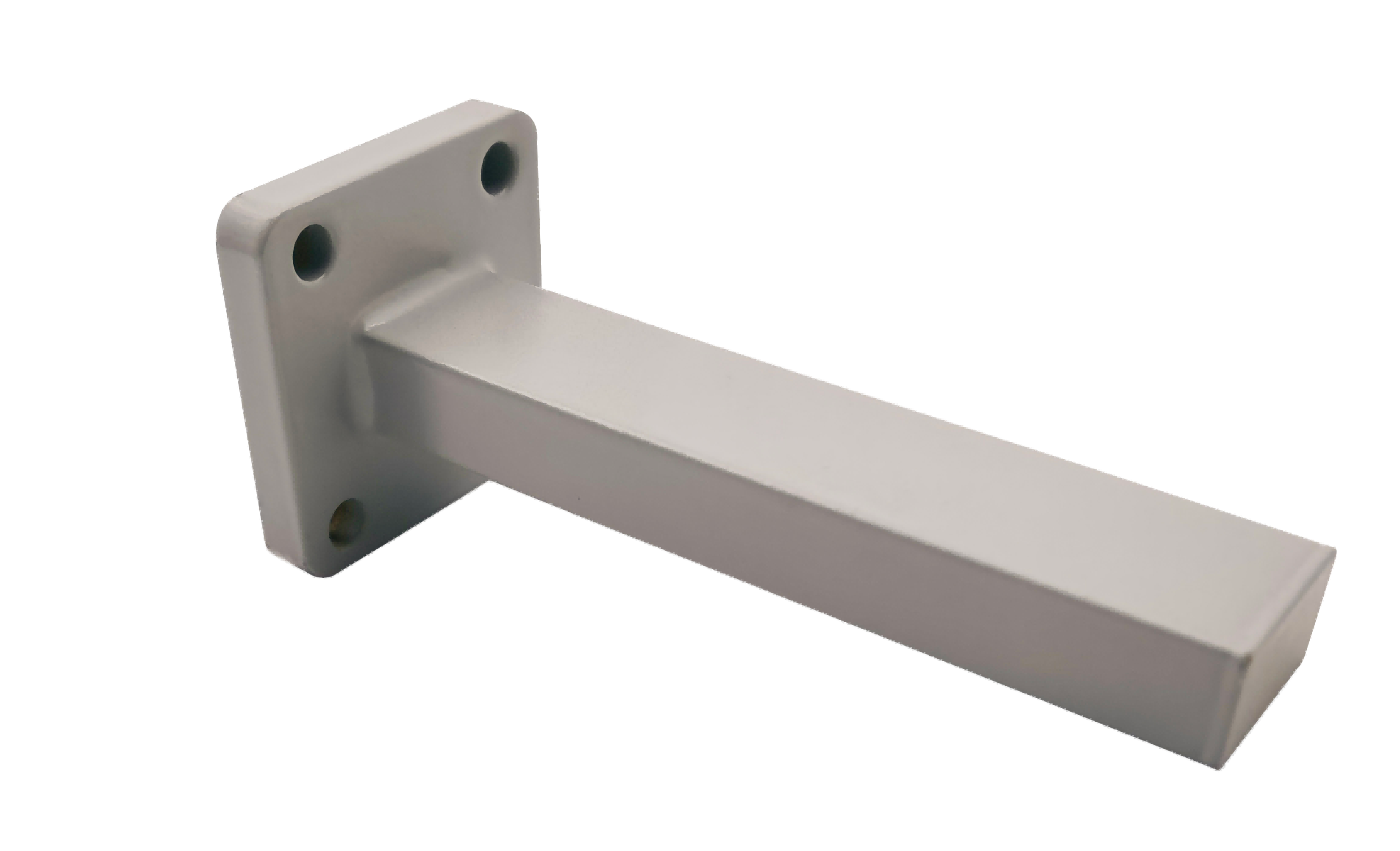
To meet diverse mechanical and environment-specific demands, we offer waveguides manufactured from high-quality metals and finished with advanced anti-corrosion protective coatings:
- Aluminum: The standard industry choice for aerospace payloads and airborne radar systems, offering an excellent balance of lightweight structural strength and high conductivity.
- Copper: Preferred for high-power, high-frequency applications requiring ultra-low signal attenuation and optimal thermal dissipation.
- Stainless Steel: Supplied in specialized cryogenic, military, or highly corrosive environments where extreme physical durability and thermal isolation are required.
- Surface Finishing & Plating: Options include high-purity silver plating (to reduce surface skin-depth losses in mmWave bands), gold plating (to maintain consistent contact resistance), passivation, and weather-proof epoxy paint.
| Part No | Frequency/GHz | VSWR (Max) | IL/dB (Max) | Length Optional/mm | Flange Type |
|---|---|---|---|---|---|
| AO2300-WALXPPACG | 0.32-0.49 | 1.1 | 0.2 | 0.2~500 | UDR3 |
| AO2100-WALXPPACG | 0.35-0.53 | 1.1 | 0.2 | 0.2~500 | UDR4 |
| AO1800-WALXPPACG | 0.41-0.62 | 1.1 | 0.2 | 0.2~500 | UDR5 |
| AO1500-WALXPPACG | 0.49-0.75 | 1.1 | 0.2 | 0.2~500 | UDR6 |
| AO1150-WALXPPACG | 0.64-0.98 | 1.1 | 0.2 | 0.2~500 | UDR8 |
| AO975-WALXPPACG | 0.75-1.15 | 1.1 | 0.2 | 0.2~500 | UDR9 |
| AO770-WALXPPACG | 0.96-1.46 | 1.1 | 0.2 | 0.2~500 | UDR12 |
| AO650-WALXPPACG | 1.13-1.73 | 1.1 | 0.2 | 0.2~2000 | UDR14 |
| AO510-WALXPPACG | 1.45-2.20 | 1.1 | 0.2 | 0.2~2000 | UDR18 |
| AO430-WALXPPACG | 1.72-2.61 | 1.1 | 0.2 | 0.1~2000 | UDR22 |
| AO340-WALXPPACG | 2.17-3.30 | 1.1 | 0.2 | 0.1~2000 | UDR26 |
| AO284-WALXPPACG | 2.60-3.95 | 1.1 | 0.2 | 0.1~2000 | UDR32 |
| AO229-WALXPPACG | 3.22-4.90 | 1.1 | 0.2 | 0.1~2000 | UDR40 |
| AO187-WALXPPACG | 3.94-5.99 | 1.1 | 0.2 | 0.1~2000 | UDR48 |
| AO159-WALXPPACG | 4.64-7.05 | 1.1 | 0.2 | 0.1~2000 | UDR58 |
| AO137-WALXPPCSG | 5.38-8.17 | 1.1 | 0.3 | 0.1~2000 | UDR70 |
| AO112-WALXPPCSG | 6.57-9.99 | 1.1 | 0.3 | 0.1~2000 | UBR84 |
| AO90-WALXPPCSG | 8.20-12.5 | 1.1 | 0.3 | 0.1~2000 | UBR100 |
| AO75-WALXPPCSG | 9.84-15.0 | 1.1 | 0.3 | 0.1~2000 | UBR120 |
| AO62-WALXPPCSG | 11.9-18.0 | 1.1 | 0.3 | 0.1~1000 | UBR140 |
| AO51-WALXPPCSG | 14.5-22.0 | 1.1 | 0.3 | 0.1~1000 | UBR180 |
| AO42-WALXPPCSG | 17.6-26.7 | 1.1 | 0.3 | 0.1~1000 | UBR220 |
| AO34-WALXPPCSG | 21.7-33.0 | 1.1 | 0.3 | 0.1~1000 | UBR260 |
| AO28-WALXPPCSG | 26.5-40.0 | 1.1 | 0.3 | 0.1~1000 | UBR320 |
| AO22-WALXPPCG | 33.0-50.0 | 1.15 | 0.5 | 0.1~500 | UG-383/U |
| AO19-WALXPPCG | 40.0-60.0 | 1.15 | 0.5 | 0.1~500 | UG383/UM |
| AO15-WALXPPCG | 50.0-75.0 | 1.15 | 0.5 | 0.1~500 | UG385/U |
| AO12-WALXPPCG | 60.0-90.0 | 1.15 | 0.5 | 0.1~500 | UG-387/U |
| AO10-WALXPPCG | 75.0-110.0 | 1.15 | 0.5 | 0.1~500 | UG387/UM |
| AO8-WALXPPCG | 92.0-140.0 | 1.15 | 0.5 | 0.1~500 | UG387/UM |
| AO6-WALXPPCG | 113.0-173.0 | 1.15 | 0.5 | 0.1~500 | UG387/UM |
| AO5-WALXPPCG | 145.0-220.0 | 1.15 | 0.5 | 0.1~500 | UG387/UM |
| AO4-WALXPPCG | 172.0-261.0 | 1.15 | 0.5 | 0.1~500 | UG387/UM |
| AO3-WALXPPCG | 217.0-330.0 | 1.15 | 0.5 | 0.1~500 | UG387/UM |
Straight Waveguide Selection & Engineering Guidelines
When integrating straight waveguide sections into high-frequency systems, several critical mechanical and electrical constraints must be evaluated to maintain system efficiency:
Determining Waveguide Frequency Bounds
For reliable signal integrity, the operational frequency should stay within 1.25 to 1.9 times the dominant mode cutoff frequency (TE10). Operating below this cutoff blocks signal propagation entirely, while exceeding the upper frequency boundary risks exciting higher-order transmission modes, causing distortion and phase variance.
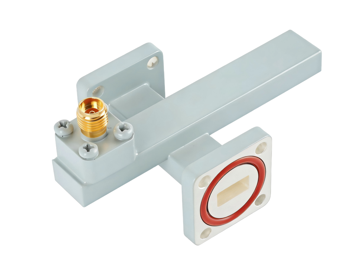
Ensuring Flange Interface Compatibility
Flange matching must be exact to secure a low VSWR. We offer precise manufacturing compatible with international standards, including UG military styles (such as UG-381/U), CPR commercial telecom configurations (pressurized/non-pressurized), and European IEC-standard equivalents like UBR/PBR. Precise pin alignment is critical at millimeter-wave frequencies (E-band, W-band) to prevent interface steps.
Overcoming Key RF & Millimeter-Wave Design Pain Points
Based on engineering challenges frequently highlighted on aerospace and hardware design forums like Reddit and Quora, we optimize our waveguides to resolve operational bottlenecks:
The Challenge of Flange Alignment and VSWR Spikes
Even a tiny alignment offset of 0.1 mm at a waveguide junction can introduce an impedance step, triggering signal reflection and unpredictable VSWR spikes. AO Microwave combats this physical mismatch by holding flange machining tolerances to a precise ±0.02 mm and utilizing advanced dowel-pin alignment methods. This level of physical precision guarantees smooth wave transitions and minimizes return loss.
Addressing Surface Attenuation in High-Frequency Systems
At high frequencies, such as E-band (60–90 GHz) and W-band (75–110 GHz), electromagnetic waves travel within a shallow "skin depth" of less than one micron on the waveguide inner walls. At this level, high surface roughness acts as a significant barrier, increasing attenuation. Our specialized internal finishing minimizes surface roughness, helping keep actual insertion losses near theoretical performance minimums.
Eliminating Lead Time Bottlenecks for Custom Lengths
Engineers and test labs often struggle with 8-to-12-week lead times for custom-length waveguide shims and straight lines. AO Microwave provides flexible, fast-turnaround prototyping and custom-length cutting options. This ensures you receive high-performance, tailored waveguide segments in weeks rather than months, keeping your project schedules on track.
Target Applications & System Integration
Our straight waveguides are key building blocks in high-power, high-frequency layouts where coaxial cables fail due to high losses or power limitations:
- Satellite Ground Stations & Payloads: Low insertion loss waveguide runs designed to handle high continuous-wave (CW) uplink power in Ka-band, Ku-band, and Q/V-band installations.
- Aerospace & Defense Radar Systems: Ruggedized, lightweight mechanical designs capable of withstanding extreme vibration and thermal cycles in airborne or naval radars.
- Millimeter-Wave Test Setups & Labs: Precision-crafted test-bench components designed for highly repeatable measurements on Vector Network Analyzers (VNAs) and spectrum analyzers.
Straight Waveguide FAQs
Need straight waveguide sections for your system?
Tell us WR size, length, flange type and quantity — we'll quote within 24 hours.