
The Hidden Cost of Mismatched Terminations: A Strategic Guide to Specifying Waveguide Loads
Stop over-engineering your RF system. Learn how to specify waveguide loads by balancing thermal dynamics, peak power, and VSWR for smart, reliable design.
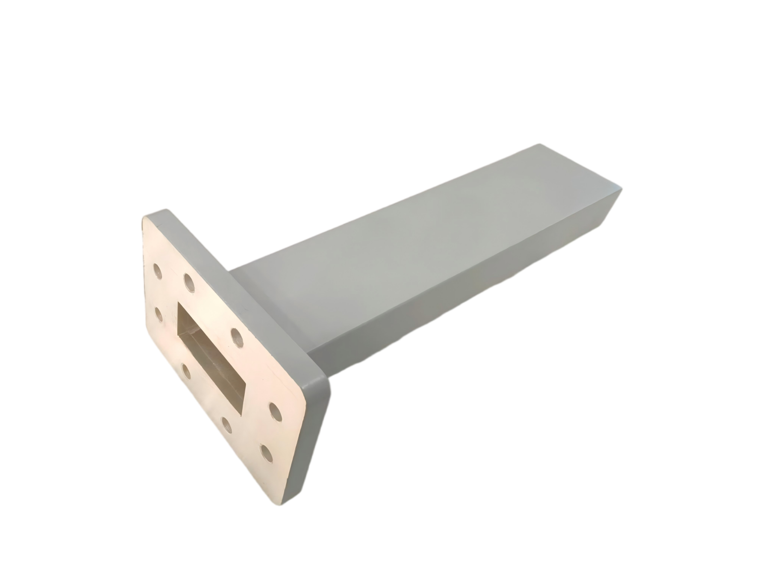
The Hidden Cost of Mismatched Terminations: A Strategic Guide to Specifying Waveguide Loads
In the rigorous discipline of RF and microwave engineering, system integrators spend months optimizing the forward transmission path. From selecting the perfect High-Power Amplifier (HPA) to fine-tuning the antenna feed, every component is scrutinized to ensure maximum signal integrity.
Yet, one of the most critical vulnerabilities in any complex RF architecture is often treated as an afterthought: the management of unused or reflected energy.
When electromagnetic energy reaches an open port on a directional coupler, a circulator, or a redundancy switch, it does not simply disappear. It reflects backward with devastating efficiency. This reflected power creates severe Voltage Standing Wave Ratio (VSWR) spikes that can corrupt Vector Network Analyzer (VNA) calibration data, induce phase distortion, and send lethal thermal stress back into your transmitters.
To neutralize this threat, engineers must deploy waveguide loads (matched terminations). However, selecting the right load is a complex exercise in balancing thermodynamics, mechanical constraints, and electromagnetic precision. Specifying the wrong component can lead to catastrophic thermal meltdowns or needlessly inflate your project budget.
In this strategic selection guide, we will move beyond basic datasheets. We will explore the critical engineering trade-offs involved in sizing waveguide loads, helping you protect your mission-critical equipment while keeping your supply chain agile and responsive.
Step 1: The Physics of the Match (Frequency & WR Size)
The foundational step in specifying a waveguide load is aligning it with your system's operating frequency. Because waveguides act as high-pass filters, the internal absorptive element of the load is geometrically tuned to absorb specific wavelengths.
You must select the correct Electronic Industries Alliance (EIA) standard size, denoted by the "WR" (Waveguide Rectangular) prefix. Your supplier must possess the manufacturing capability to support your specific band with absolute precision:
- S, C, and X-Band (2.60 - 12.40 GHz): Covering WR-284 to WR-90. The industry standard for marine radar, weather monitoring, and EMC immunity testing.
- Ku and Ka-Band (10.0 - 40.0 GHz): Covering WR-75 to WR-28. Essential for high-throughput LEO satellite constellations and 5G mmWave backhaul networks.
- V, E, and W-Band (40.0 - 110.0 GHz): Covering WR-19 down to WR-10. Critical for advanced automotive radar, 6G research, and ultra-high-resolution imaging.
Step 2: Thermodynamics and Power Handling (The Peak vs. CW Dilemma)
A waveguide load functions by forcing the electromagnetic wave into a tapered resistive material (such as carbon-impregnated ceramics). The laws of thermodynamics dictate that 100% of this absorbed RF energy is converted directly into heat.
Therefore, choosing the right load is fundamentally a thermal management decision. If a load cannot dissipate heat faster than it absorbs it, the internal element will crack or melt, turning the load into an open circuit and leaving your transmitter unprotected.
One of the most dangerous mistakes in specifying a high-power dummy load is focusing solely on Average Power (Continuous Wave / CW). In pulsed radar systems, the Average Power might only be 100 Watts, but the Peak Power during the microsecond pulse could be 100 Kilowatts. If the load is not rated for that peak voltage, the intense electric field will ionize the air inside the waveguide, causing catastrophic electrical arcing (sparking) that will destroy both the load and the transmitter. Always specify both CW and Peak power requirements!
Low-Power Terminations vs. High-Power Dummy Loads
For terminating the isolated ports of directional couplers or switches, a compact, un-finned Low-Power Load (1W to 50W) is sufficient. However, if you are performing offline calibration of a radar transmitter, you need a High-Power Dummy Load. These feature massive extruded aluminum cooling fins to maximize natural convection cooling, and may even require forced-air fans for extreme kilowatt applications.
Step 3: The VSWR Imperative (Where Precision Matters)
The true measure of a waveguide load's quality is its Voltage Standing Wave Ratio (VSWR). A perfect load has a VSWR of 1.0:1, meaning zero reflection. Achieving a near-perfect match requires uncompromising CNC machining of the waveguide housing and exact geometric tapering of the absorptive element.
When protecting sensitive equipment or establishing baseline measurements, sourcing precision waveguide loads with guaranteed low VSWR is non-negotiable. However, smart specifying means knowing exactly how much precision your application actually requires:
| Application Scenario | Recommended VSWR | Engineering Rationale |
|---|---|---|
| VNA Calibration & Metrology | < 1.03:1 | In a laboratory, the load acts as the absolute reference standard. Any reflection here will permanently skew all subsequent measurements. You must demand maximum precision. |
| Satcom 1:1 Redundancy Isolation | < 1.10:1 | When terminating a standby amplifier, you need excellent absorption to prevent leakage into the active transmission path, ensuring pristine signal-to-noise ratios. |
| General Transmitter Dummy Loads | < 1.15:1 to 1.20:1 | When running a radar transmitter into a dummy load for offline maintenance, the primary goal is safe heat dissipation. A VSWR of 1.15 is more than sufficient to protect the magnetron. |
Step 4: Mechanical Integrity (Flanges and Materials)
A brilliant electrical termination is useless if the mechanical connection is flawed. A mismatched or poorly seated flange will introduce microscopic air gaps, leading to impedance variations and dangerous RF leakage.
- Material Selection: Choose Aluminum for lightweight applications (like UAV payloads or aviation). Choose Copper or Brass for maximum thermal conductivity in high-power continuous wave (CW) applications.
- Flange Compatibility: Ensure the flange matches your existing architecture perfectly. For standard frequencies, specify UDR, UBR, or Cover/Choke flanges. For millimeter-wave frequencies (above 40 GHz), you must specify precision anti-cocking flanges (such as the UG-387/U) with exact alignment pins to guarantee a flush, leak-proof mechanical seal.
Step 5: Overcoming Supply Chain Fragility with Agile Manufacturing
Designing a flawless RF architecture is a significant engineering achievement. However, the true challenge for system integrators today is securing these precision components on time to meet strict project deadlines.
For decades, the RF industry has relied on a handful of legacy Western manufacturers. While their quality is established, their rigid, bureaucratic supply chains often result in agonizing 16 to 24-week lead times. When you are deploying a new satellite earth station or upgrading a critical EMC test bench, waiting half a year for a precision waveguide load is unacceptable. It stalls projects, frustrates stakeholders, and delays your time-to-market.
You need a partner who matches your engineering rigor with manufacturing agility.
We believe that your supplier should be a strategic partner, not a bottleneck. As a true source manufacturer, AO Microwave offers deep customization capabilities across the entire spectrum—from 0.32 GHz all the way up to 110 GHz. Whether you need an ultra-low VSWR standard load for VNA calibration, or a custom-finned dummy load optimized for high-altitude thermal derating, our engineering team can design and manufacture the exact component you need. Combined with our agile manufacturing process, we deliver these tailored, industrial-grade solutions rapidly, ensuring your project stays on schedule without compromising on equipment safety.
Conclusion: Specify with Intelligence, Protect Your Architecture
Choosing the right waveguide load is not about blindly picking the highest specs from a catalog; it is about intelligent engineering. By carefully weighing the trade-offs between thermal dissipation, peak power handling, and the exact VSWR your application demands, you can optimize your system's performance while keeping your budget under control.
By partnering with an agile, source manufacturer like AO Microwave, you gain the flexibility to customize your components to your exact architectural needs, breaking free from the constraints and long lead times of legacy suppliers.
Ready to Safeguard Your RF System?
Don't let thermal failures or rigid supply chains delay your project launches. Whether you need precision Standard Loads for a Satcom routing matrix, or massive High-Power Dummy Loads for radar calibration, AO Microwave has the expertise and manufacturing agility to deliver exactly what you need.
Contact our engineering team today to discuss your specific power and environmental requirements, and let us provide the perfect tailored solution for your RF system.