
Are Hidden Routing Errors Killing Your RF System? Common Problems in Waveguide Bends and How to Avoid Signal Loss
Are waveguide bends causing VSWR spikes and phase distortion in your RF system? Discover the root causes of signal loss in E-bends and H-bends, and learn how precision CNC routing solves it.
Are Hidden Routing Errors Killing Your RF System? Common Problems in Waveguide Bends and How to Avoid Signal Loss
Routing rigid transmission lines through cramped mechanical enclosures is one of the most frustrating challenges in RF engineering. Whether your integration facility is located in the aerospace corridors of Southern California, the telecom hubs of Europe, or anywhere across the global supply chain, the physical constraints of your chassis remain the same: you must navigate tight corners without destroying your signal integrity.
To achieve this, engineers rely on Waveguide Bends. However, a quick glance at engineering forums like Reddit’s r/rfelectronics or Quora reveals a recurring nightmare: system integrators frequently experience unexplained Voltage Standing Wave Ratio (VSWR) spikes, phase distortion, and severe insertion loss the moment they introduce a bend into their waveguide run.
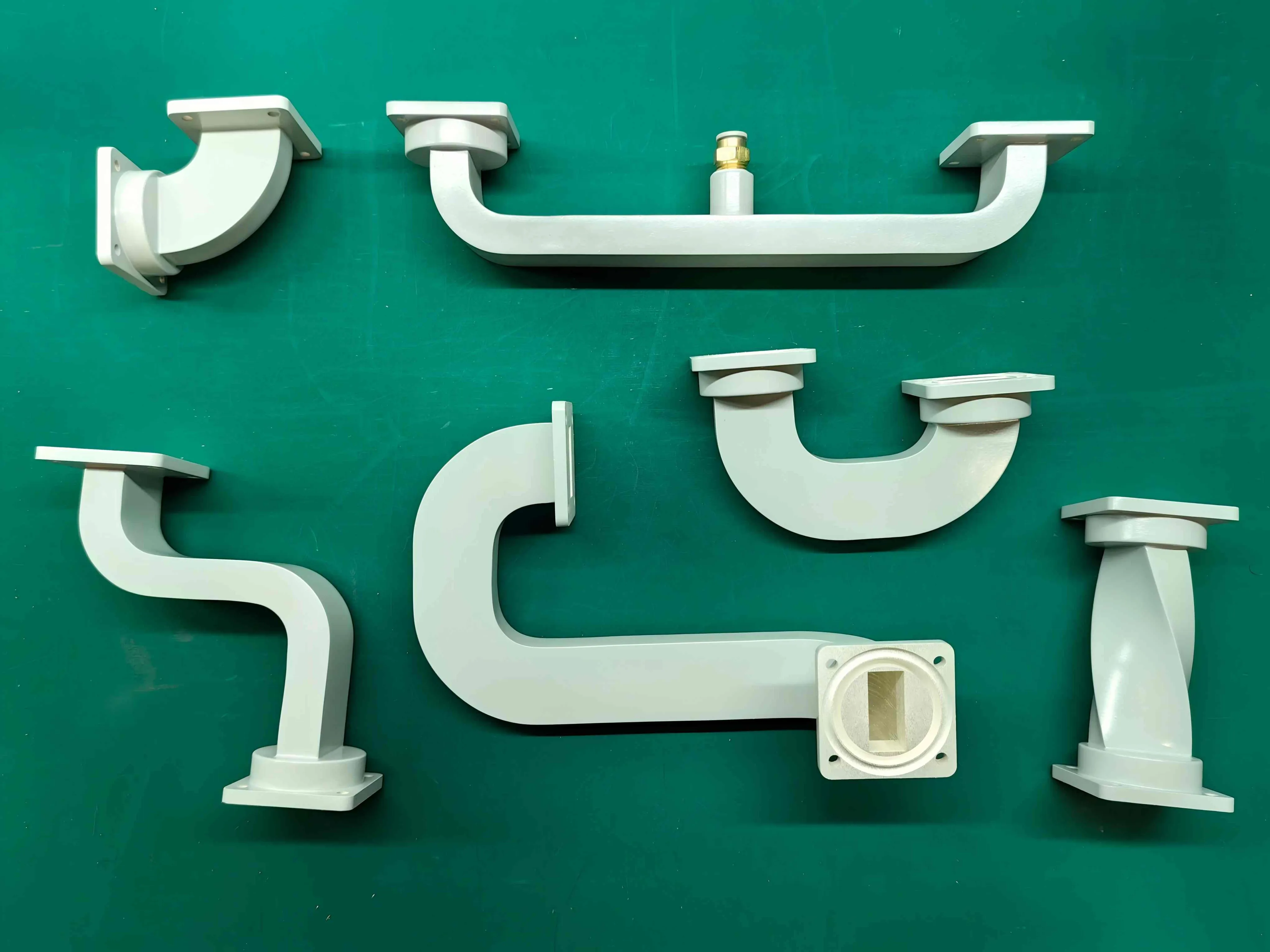
A waveguide bend is never just a "bent pipe." It is a highly sensitive electromagnetic structure. When manufactured poorly, it acts as a roadblock for high-frequency energy, reflecting lethal power back into your expensive amplifiers.
If you are asking, "What are the common problems in waveguide bends and how can I avoid signal loss?", this diagnostic guide is for you. We will explore the physics behind the four most common routing failures, explain why H-bends are notoriously difficult to master, and demonstrate how partnering with an agile, precision manufacturer can safeguard your mission-critical architecture.
Problem 1: Cross-Sectional Deformation (The VSWR Spike)
The most frequent cause of signal loss in a waveguide bend is the deformation of its internal cross-section. In the dominant TE10 mode, the electromagnetic wave relies on the exact internal dimensions (the broad wall 'a' and narrow wall 'b') to maintain its characteristic impedance.
When a manufacturer uses inferior bending techniques (such as bending without a proper internal mandrel), the metal at the apex of the curve tends to wrinkle, flatten, or collapse. Even a microscopic deformation changes the impedance at the curve. When the RF signal hits this impedance mismatch, a significant portion of the energy reflects backward, creating a massive VSWR spike.
Problem 2: The H-Bend Cutoff Frequency Trap
A common question among junior RF engineers is: "Why does my H-Bend fail testing while my E-Bend passes perfectly?"
The answer lies in the physics of the electromagnetic field. An H-Bend (Magnetic Plane Bend) curves along the narrow wall, meaning the broad wall (the 'a' dimension) is the surface being bent. In waveguide theory, the broad wall dictates the cutoff frequency—the lowest frequency that can propagate through the waveguide.
If an H-bend is poorly machined and the broad wall shrinks even slightly during the bending process, the cutoff frequency shifts higher. This inadvertently "chokes off" the lower frequencies of your operating band, causing catastrophic insertion loss. Conversely, E-Bends bend along the broad wall (altering the 'b' dimension), which does not affect the cutoff frequency. This makes a precision Waveguide E-Bend inherently more forgiving to manufacture and integrate.
Problem 3: Phase Distortion in mmWave Applications
As 5G networks and automotive radar systems push into millimeter-wave (mmWave) frequencies (Ka, V, E, and W bands), the physical length of the wave shrinks to mere millimeters. At these frequencies, the path length difference between the inner radius and the outer radius of a swept bend becomes highly significant.
If the radius of the bend is not mathematically optimized (typically > 2λ), the wave traveling along the outer edge falls out of sync with the wave on the inner edge. This causes severe Phase Distortion. In phased array radar systems or complex antenna feed networks, phase errors will completely destroy the beamforming accuracy and antenna radiation pattern.
How to Avoid It: For phase-critical applications, engineers must specify custom swept bends with a precisely calculated radius. Alternatively, precision Mitered Bends (Right-Angle Bends) can be used in ultra-compact spaces, provided the mitered corner is CNC-machined to exact theoretical dimensions to reflect the wave perfectly without phase lag.
Problem 4: Mechanical Stress and Flange Arcing
Waveguide bends are often used to bridge gaps between misaligned components. A common, yet dangerous, practice is "forcing" a slightly misaligned bend to bolt onto an amplifier or antenna feed. This places immense mechanical torque on the waveguide flanges.
Over time, this stress warps the flange face, creating microscopic air gaps. At high power levels, RF energy leaks out of these gaps, causing interference. Worse, the intense electric field can ionize the air in the gap, causing Flange Arcing (sparking), which will permanently pit and destroy the mating surfaces.
Overcoming Supply Chain Fragility with Agile Manufacturing
Diagnosing routing errors is only half the battle; securing the right precision components on time is the other. For decades, system integrators in North America and Europe have endured 16 to 24-week lead times from legacy Western manufacturers for custom waveguide bends. When you are racing to deploy a new satellite earth station or upgrade a critical EMC test bench, waiting half a year for a specific H-bend is unacceptable. It stalls projects, frustrates stakeholders, and delays your time-to-market.
You need a partner who matches your engineering rigor with manufacturing agility.
At AO Microwave, we redefine industrial-grade reliability. We manufacture premium E-Bends, H-Bends, Swept, and Mitered waveguide assemblies with uncompromising precision. By combining advanced CNC machining with an agile, streamlined manufacturing process, we deliver the ultra-low VSWR and pristine phase stability your systems demand—without the crippling lead times of legacy brands. We empower your engineering teams to stay on schedule, keep your networks online, and execute with confidence.
Conclusion: Route with Precision, Protect Your Signal
In the high-stakes world of microwave engineering, a waveguide bend is the critical connective tissue of your RF architecture. By understanding the common pitfalls—cross-sectional deformation, H-bend cutoff choking, phase distortion, and flange stress—engineers can proactively specify the correct components to protect their signal integrity.
By partnering with an agile manufacturer dedicated to industrial-grade excellence, you can build a resilient, high-performance RF system that navigates the tightest enclosures and is delivered on time, every time.
Ready to Solve Your Complex RF Routing Challenges?
Don't let hidden routing errors degrade your signal, and don't let rigid supply chains delay your project launches. Whether you need precision Swept E-Bends for a high-power Satcom uplink or ultra-compact Mitered H-Bends for a 5G transceiver, AO Microwave delivers the reliability and responsiveness you need.
Contact Our Engineering Team