
The Essential Guide: How Waveguide Dimensions Determine Frequency Performance
Waveguides are fundamental components in modern electromagnetic systems, serving as the highways for high-frequency signals in applications ranging from radar installations to satellite communications and medical imaging. The relationship between a waveguide's physical dimensions and its frequency characteristics forms the cornerstone of effective electromagnetic design. This intricate dance between metal structures and electromagnetic waves dictates how signals propagate, attenuate, or get blocked entirely in various engineering applications.
1. The Fundamental Principle: Waveguide as a High-Pass Filter
Waveguides exhibit a fascinating property: they function as natural high-pass filters for electromagnetic energy. This means they readily allow higher-frequency signals to pass while blocking or attenuating lower-frequency signals. The transition point between these two behaviors is known as the cutoff frequency—a critical parameter determined almost exclusively by the waveguide's cross-sectional dimensions
.
Below this cutoff frequency, electromagnetic waves experience exponential attenuation as they travel through the waveguide, making transmission impractical. Above the cutoff frequency, waves propagate with minimal attenuation, allowing efficient signal transmission. This frequency-dependent behavior stems from solving Maxwell's equations with the waveguide's boundary conditions, where only specific electromagnetic field patterns (modes) can exist at given frequencies
.
2. Cutoff Frequency Formulas for Different Waveguide Shapes
The mathematical relationship between dimensions and cutoff frequency varies according to the waveguide's cross-sectional shape. For practical engineering applications, three primary shapes dominate:
-
Rectangular Waveguides (most common in microwave systems):
fc = 15 × 10⁹ / l (Hz)
Where l is the longer side dimension in centimeters.
For TE₁₀ mode (the dominant mode), the cutoff frequency depends solely on the wider dimension 'a':
fc = c / (2 × a × √εᵣ)
where c is light speed (3×10⁸ m/s), a is the wider dimension in meters, and εᵣ is the relative permittivity of the medium inside. -
Circular Waveguides:
fc = 17.6 × 10⁹ / d (Hz)
Where d is the inner diameter in centimeters.
In practical engineering units: fc = 6900 / D (MHz) with D in inches. -
Hexagonal Waveguides (common in honeycomb ventilation panels):
fc = 15 × 10⁹ / w (Hz)
Where w is the distance across opposite sides in centimeters.
These formulas reveal a crucial inverse relationship: larger dimensions result in lower cutoff frequencies. This explains why waveguides for microwave frequencies (GHz range) appear as small metal pipes, while those for lower frequencies would be impractically large
.
3. The Critical Role of Waveguide Length in Shielding
When waveguides are used for electromagnetic shielding—as in ventilation panels (waveguide vents) or fiber optic penetrations—their length becomes equally important as cross-sectional dimensions. The waveguide's attenuation capability for frequencies below cutoff depends directly on its length-to-diameter ratio
.
The absorption loss (A) for signals below cutoff is calculated as:
-
General formula:
A = 1.8 × fc × t × 10⁻⁹ × [1 - (f/fc)²]¹ᐟ² (dB)
Where t is length in cm, f is signal frequency, and fc is cutoff frequency. -
Simplified for f << fc (f < fc/5):
Circular waveguides: A = 32 × t / d (dB)
Rectangular/Hexagonal waveguides: A = 27 × t / l (dB)
(t and d/l in consistent units).
These equations reveal a remarkable relationship: attenuation increases by approximately 30 dB when waveguide length increases by one cross-section dimension (e.g., one diameter for circular guides)
. This explains the engineering rule-of-thumb: L/D > 5 ensures complete electromagnetic shielding
.
4. Practical Design Considerations
Designing effective waveguide-based systems requires balancing multiple factors:
-
Safety margin: For shielding applications, the cutoff frequency should be 5-10 times higher than the highest frequency needing attenuation
. This ensures sufficient attenuation across the entire frequency range. -
Length requirements: Waveguide length should be at least 3 times the cross-sectional dimension (≥3d for circular guides) to provide adequate shielding
. Military-grade shielding (≥100 dB) requires substantially longer waveguides than commercial applications (≥80 dB). -
Material and construction: Waveguides must be constructed from highly conductive materials (copper, brass, or aluminum with silver plating) to minimize resistive losses
. Surface conductivity at waveguide openings is critical—any contamination can dramatically reduce shielding effectiveness. -
Avoiding common mistakes: Never run conductive elements (wires, cables) through cutoff waveguides intended for shielding, as this creates severe electromagnetic leakage paths
. Ensure waveguide walls are sufficiently thick to prevent mechanical deformation that could alter dimensions and thus frequency characteristics.
5. Real-World Applications
Understanding the dimension-frequency relationship enables several key applications:
-
EMC Shielding: Waveguide vents in electromagnetic shielding rooms use honeycomb structures (hexagonal waveguides) sized to block interference frequencies while allowing airflow. A typical design might use 0.3 cm hexagonal cells to attenuate frequencies up to 10 GHz
. -
Microwave Systems: Radar waveguides are precisely dimensioned rectangular tubes that only propagate frequencies above cutoff. WR-90 waveguide (common in X-band systems) has dimensions 2.286 cm × 1.016 cm, giving a TE₁₀ cutoff frequency of 6.56 GHz
. -
High-Power Transmission: Large circular waveguides transmit high-power microwave signals over distances with minimal loss, crucial for satellite communications and particle accelerators. Their diameter determines both power-handling capacity and frequency range
. -
Slot Antennas: Waveguides with precisely spaced slots become directional antennas for radar systems, where slot dimensions and spacing determine radiation patterns and operating frequencies
.
The elegant relationship between waveguide dimensions and frequency behavior demonstrates how fundamental physics principles translate into practical engineering solutions. By manipulating simple geometric parameters, engineers can control electromagnetic wave propagation with remarkable precision—enabling technologies from everyday microwave ovens to cutting-edge satellite communications. As frequency demands continue increasing with 5G/6G systems and beyond, the precise dimensional control of waveguides remains more critical than ever for effective electromagnetic design.
 What Types of Coaxial Suspension Line Filters Are Available for RF and Microwave Systems?
 Why Are Coaxial Suspension Line Filters the Right Choice for High-Performance RF Systems?
 What's the Coaxial Suspension Line Filter?
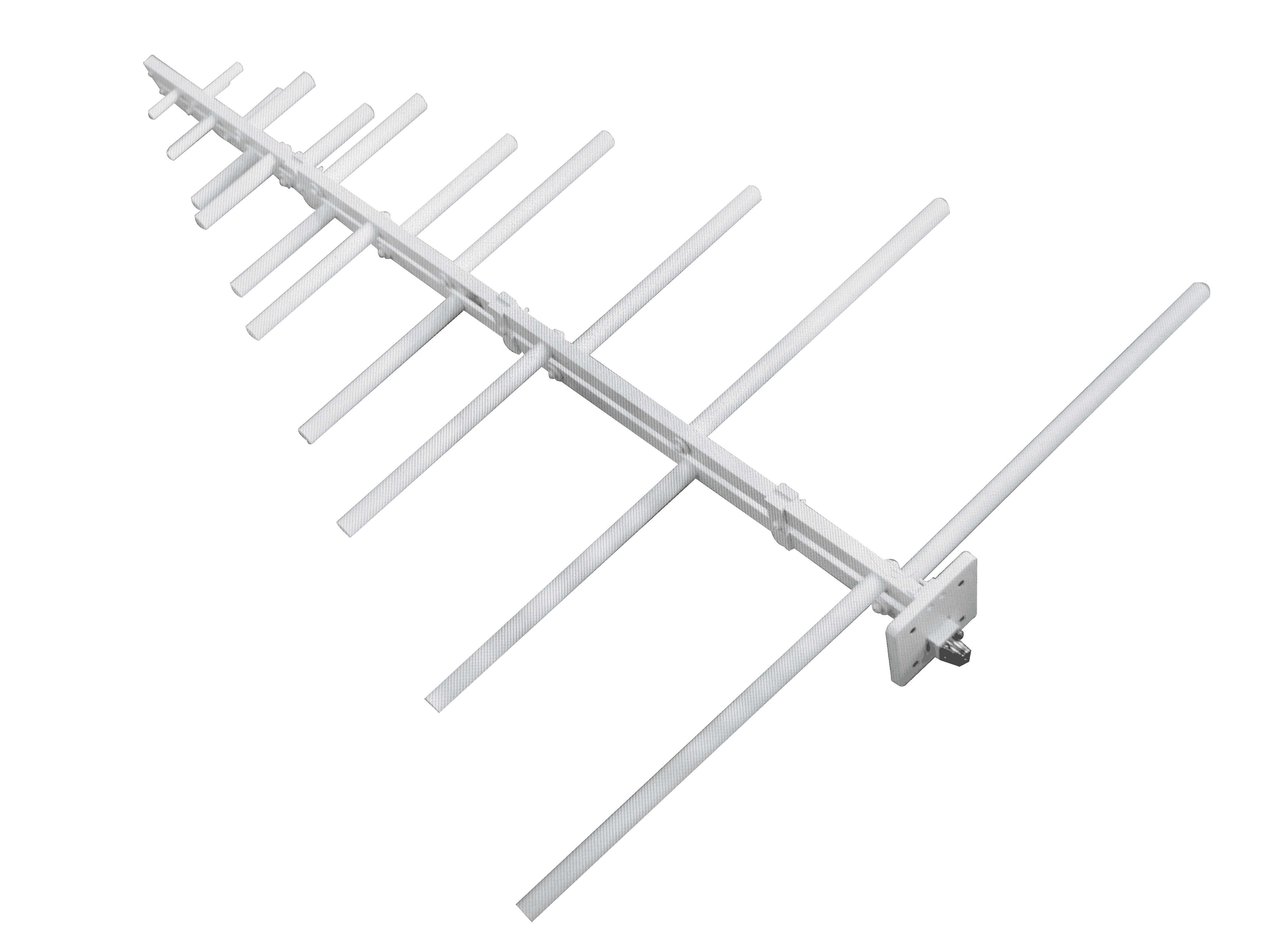 How to Choose a Log-Periodic Antenna for Long-Range Communication?