
Are Hidden Routing Errors Degrading Your Satcom Network? Why Waveguide Bends Matter in Microwave and Satellite Systems
Why do waveguide bends matter in microwave and satellite systems? Learn how precision E-bends and H-bends prevent VSWR spikes and protect signal integrity.
Are Hidden Routing Errors Degrading Your Satcom Network? Why Waveguide Bends Matter in Microwave and Satellite Systems
When engineering teams design a state-of-the-art satellite earth station or a 5G mmWave telecommunications hub, the spotlight naturally falls on the active components. Millions of dollars are invested in ultra-linear High-Power Amplifiers (HPAs), low-noise block downconverters (LNBs), and massive parabolic reflectors.
However, the most sophisticated amplifier in the world is entirely useless if the electromagnetic energy it generates cannot be efficiently routed to the antenna. In the real world, transmission lines rarely run in a straight, unobstructed path. They must navigate through cramped equipment racks, bypass structural pillars, and snake through complex building conduits.
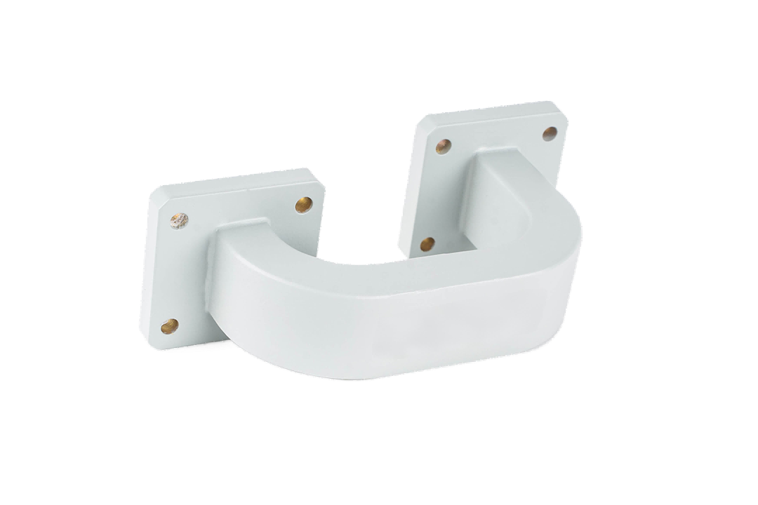
Because rigid waveguides cannot be flexed like coaxial cables, system integrators must rely on a highly specialized component to change the direction of the signal: the Waveguide Bend.
Often dismissed as mere "plumbing," waveguide bends are actually complex electromagnetic structures. A poorly manufactured bend is a silent killer of signal integrity. It introduces phase distortion, triggers severe Voltage Standing Wave Ratio (VSWR) spikes, and can reflect lethal power back into your transmitters.
If you are asking, "Why do waveguide bends matter so much in microwave and satellite systems?", this comprehensive guide will provide the answers. We will explore the unforgiving physics of RF routing, decode the critical differences between E-plane and H-plane bends, and demonstrate how partnering with an agile, industrial-grade manufacturer can safeguard your network's reliability while keeping your project timelines strictly on track.
The Physics of the Curve: Why a Bend is Never Just a "Pipe"
To understand the critical importance of a waveguide bend, we must first look at how electromagnetic energy travels inside a rectangular waveguide. In the dominant operating mode (TE10), the wave propagates through the hollow metallic cavity, relying on the exact internal dimensions (the broad wall 'a' and the narrow wall 'b') to maintain its characteristic impedance.
When an electromagnetic wave encounters a curve, the physics change dramatically. The wave traveling along the outer radius of the bend must cover a longer distance than the wave traveling along the inner radius. If the bend is not mathematically calculated and precisely machined, this path difference causes Phase Distortion.
The greatest threat during the manufacturing of a waveguide bend is the deformation of the internal cross-section. If the metal wrinkles, flattens, or collapses even slightly at the apex of the curve, the impedance of the waveguide changes instantly. When the high-power RF signal hits this impedance mismatch, it reflects backward. In a multi-kilowatt satellite uplink, this reflected energy creates massive VSWR spikes that can cause thermal overload and catastrophic arcing inside your High-Power Amplifier. A premium waveguide bend must change direction while maintaining absolute dimensional perfection.
Critical Applications: Where Waveguide Bends Make or Break the System
With the global satellite communication market expanding rapidly—driven by Low Earth Orbit (LEO) constellations and high-throughput data links—the demand for flawless RF routing has never been higher. Waveguide bends are the critical connective tissue in these environments:
1. Satellite Earth Stations (Satcom)
In a typical earth station, the HPAs are housed safely indoors in climate-controlled racks, while the antenna feed horn is located outdoors on a pedestal. The transmission line must route the high-power uplink signal (often in C, X, Ku, or Ka-band) through walls, under floors, and up the antenna structure. This requires a complex matrix of swept waveguide bends. Any insertion loss introduced by these bends directly reduces the Effective Isotropic Radiated Power (EIRP) of the station, degrading the link margin with the satellite.
2. 5G mmWave and Telecommunications
As 5G networks push into millimeter-wave frequencies (26 GHz to 40 GHz), coaxial cables become too lossy for backhaul connections. Engineers must use waveguides. However, 5G transceivers are incredibly compact. Navigating the dense internal architecture of a 5G base station requires ultra-precise, miniature waveguide bends that can route signals without introducing cross-talk or phase errors.
3. EMC / EMI Testing Chambers
In anechoic chambers, pure RF signals must be routed from the control room amplifiers to the radiating horn antennas inside the shielded room. Waveguide bends are used to navigate the thick, RF-shielded walls of the chamber. Because EMC testing requires absolute measurement accuracy, the bends must offer near-perfect VSWR to ensure the field strength calculations are not corrupted by reflected power.
The E-Bend vs. H-Bend Dilemma in System Layouts
When designing a routing architecture, engineers must specify the plane in which the bend occurs. This is dictated by the orientation of the electromagnetic field, and choosing the right component is vital for navigating 3D space:
- The E-Bend (Electric Plane Bend): Curves along the broad wall, changing the direction of the Electric field. E-bends are typically used for vertical elevation changes. For instance, when routing a signal from a floor-level rack up to a ceiling conduit, engineers rely on precision waveguide E-bends to navigate the elevation shift while maintaining absolute phase stability and ultra-low VSWR.
- The H-Bend (Magnetic Plane Bend): Curves along the narrow wall, changing the direction of the Magnetic field. H-bends are typically used for horizontal routing. When turning left or right to bypass a structural pillar in a dense equipment room, integrating high-performance waveguide H-bends ensures the magnetic field transitions smoothly without choking the bandwidth.
Swept vs. Mitered Bends: Balancing Space and Performance
System integrators must also choose the mechanical style of the bend, balancing the need for signal integrity against severe mechanical space constraints.
| Bend Configuration | Design Characteristics | Primary Application & Engineering Value |
|---|---|---|
| Swept Bend (Radius Bend) | A smooth, continuous, gradual curve (typically 90°, 45°, or custom angles). | Maximum Signal Integrity. Offers the lowest insertion loss and highest power handling. It is the undisputed choice for Satcom earth stations and high-power radar where space allows for a gradual radius. |
| Mitered Bend (Right-Angle Bend) | A sharp, hard 90-degree corner. The outer corner is "mitered" (cut at a precise angle) to reflect the wave around the corner. | Ultra-Compact Routing. Used when mechanical space is severely restricted, such as inside UAV payloads or dense 5G transceivers. While it saves space, it requires flawless machining to prevent VSWR spikes at the mitered corner. |
Overcoming Supply Chain Fragility with Agile Manufacturing
Designing a flawless RF routing architecture is a significant engineering achievement. However, the true challenge for system integrators today is securing these custom routing components on time to meet strict project deadlines.
For decades, the RF industry has relied on a handful of legacy Western manufacturers. While their quality is established, their rigid, bureaucratic supply chains often result in agonizing 16 to 24-week lead times. When you are deploying a new satellite earth station or upgrading a critical defense radar, waiting half a year for a specific 90-degree swept H-bend is unacceptable. It stalls projects, frustrates stakeholders, and delays your time-to-market.
You need a partner who matches your engineering rigor with manufacturing agility.
We believe that your system architecture should dictate the components, not the other way around. As a true source manufacturer, AO Microwave offers deep customization capabilities for both E-Bends and H-Bends across the entire spectrum (up to 110 GHz). Whether you need a specific swept radius to minimize phase distortion, an ultra-compact mitered bend for a dense enclosure, or a complex multi-bend assembly, our engineering team can design and manufacture the exact component you need. Combined with our agile manufacturing process, we deliver these tailored, industrial-grade solutions rapidly, ensuring your project stays on schedule without compromising on signal integrity.
Conclusion: Navigate Complexity with Confidence
In the high-stakes world of microwave and satellite systems, a waveguide bend is far more than a simple corner; it is a highly engineered component critical to maintaining the impedance, phase stability, and power efficiency of your entire RF architecture. By understanding the physics of E-plane and H-plane routing, and by selecting the appropriate swept or mitered configurations, engineers can overcome severe space constraints without sacrificing signal integrity.
By prioritizing critical specifications like internal cross-sectional stability and VSWR, and by partnering with an agile manufacturer dedicated to industrial-grade excellence, you can build a resilient, high-performance RF network that is delivered on time, every time.
Ready to Solve Your Complex RF Routing Challenges?
Don't let mechanical space constraints compromise your signal integrity, and don't let rigid supply chains delay your project launches. Whether you need precision Swept E-Bends for a high-power Satcom uplink or ultra-compact Mitered H-Bends for a 5G transceiver, AO Microwave delivers the reliability and responsiveness you need.
Contact our engineering team today for a technical consultation, and let us help you build a resilient, high-performance RF routing architecture.