
What Does "Phase-Stable" Mean in a 40 GHz Cable Assembly — and Why Does It Matter?
Drifting 40 GHz measurements? Learn what phase stability, insertion loss, and VSWR mean in flexible cable assemblies - and how a VSWR under 1.20 keeps calibration valid.
What Does "Phase-Stable" Mean in a 40 GHz Cable Assembly — and Why Does It Matter?
If you’ve ever watched a VNA reading drift while you flex a test cable, you know the feeling. The number you trusted five minutes ago is suddenly different. Most engineers blame the instrument. More often than not, the cable is the real culprit.
At 40 GHz, the rules change. A wavelength is only about 7.5 mm, so a 0.1 mm dimensional tolerance that was harmless at 1 GHz becomes a visible reflection point. The cable assembly — not the connectors, not the instrument — is usually the weakest link in a high-frequency measurement chain. Yet it’s the component buyers tend to specify last and think about least.
This article explains the four specifications that actually separate a good 40 GHz cable from a mediocre one — insertion loss, phase stability, amplitude stability, and VSWR — and when paying for a phase-stable, ultra-low-loss design is worth every cent.
A Recent 40 GHz Build: What "Good" Looks Like
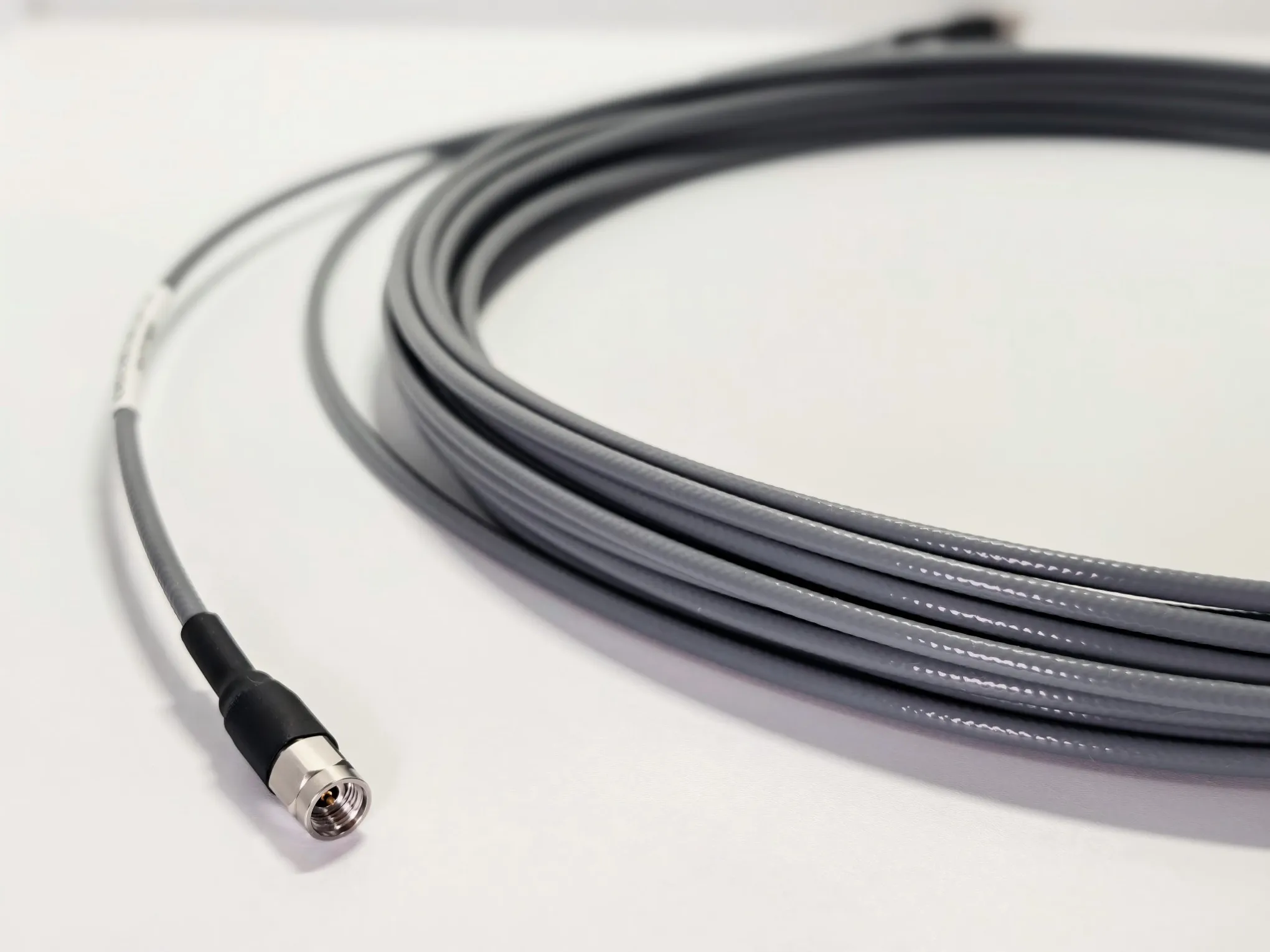
A customer running production test stations recently asked AO Microwave for two 40 GHz cable assemblies. Their requirement was straightforward: stable, repeatable measurements on a bench that sees constant handling. We built both on our CA Series ultra-low-loss, amplitude/phase-stable flexible cable platform.
The headline number: VSWR below 1.20 across the full DC–40 GHz band. For context, the common spec for this class of flexible test cable is 1.30 at 40 GHz. Getting under 1.20 took careful connector transition control and assembly workmanship — not exotic materials. It’s a real, repeatable result, and it’s the kind of performance that keeps a calibration valid all day. Here’s what each of those numbers actually means.
1. Insertion Loss: The Tax You Pay Per Meter
Insertion loss is how much signal the cable eats on the way through. It grows with frequency for two reasons: conductor resistance (worsened by the skin effect, which confines current to a thin surface layer) and dielectric losses in the insulation.
At 40 GHz, a typical flexible cable loses roughly 2.5–3 dB per meter — that’s over half the power gone in one meter. Every connector adds more. For a test engineer, this loss directly eats into dynamic range: the weaker the signal at the receiver, the noisier the measurement.
- Low-density PTFE (LD-PTFE) dielectrics cut dielectric loss significantly — one of the reasons "ultra-low-loss" cables cost more
- Silver-plated conductors reduce surface resistance where the skin effect concentrates current
- Every dB saved at 40 GHz is worth more than a dB saved at 1 GHz, because system margins shrink fast at mmWave frequencies
2. Phase Stability: The Spec Nobody Reads — Until It Fails
Phase stability describes how much a cable’s electrical length changes when it’s flexed or when temperature changes. It matters most in three situations: VNA calibration, phased-array testing, and any measurement where you compare a signal against a reference.
Here’s the practical problem. A standard cable flexed into a new position can shift phase by 10–20 degrees at 40 GHz. In a measurement setup, that shift looks exactly like a change in the device under test. You end up chasing a ghost — re-calibrating, re-measuring, doubting your results.
A phase-stable cable holds this drift to a few degrees (typically ±5–8° or better) through repeated flexing. That’s the difference between trusting your numbers and constantly re-verifying them.
3. Amplitude Stability: The Quiet Contributor
Amplitude stability is the less famous sibling of phase stability. It measures how much the cable’s loss changes as the cable moves. A cable that reads 2.80 dB flat, then 2.95 dB when lifted, then 2.85 dB when dropped back — that’s poor amplitude stability.
For antenna pattern measurements and receiver sensitivity tests, these small loss changes translate directly into false amplitude ripple across the frequency sweep. A stable cable keeps the trace flat so the data reflects the device, not the wiring. In good assemblies, amplitude stability is held within ±0.05 to 0.1 dB through flexing.
4. VSWR: The Match That Makes or Breaks the Chain
VSWR (voltage standing wave ratio) measures how well the assembly is matched to 50 ohms. A perfect match is 1.00; anything reflected back is wasted energy that shows up as ripple and uncertainty in your measurement.
| VSWR | Return Loss | Reflected Power | Verdict |
|---|---|---|---|
| 1.10 | 26.4 dB | 0.2% | Excellent |
| 1.20 | 20.8 dB | 0.8% | Very good |
| 1.30 | 17.7 dB | ~2% | Good (typical 40 GHz spec) |
| 1.50 | 14.0 dB | 4% | Acceptable for antennas only |
The gap between 1.30 and 1.20 at 40 GHz sounds small — roughly 3 dB of return loss. But in a production test station, that difference means a measurably cleaner reference plane, less ripple in S-parameter sweeps, and fewer borderline pass/fail calls on good parts.
Why does VSWR climb so fast with frequency? Because connector pins, transitions, and machining tolerances that are electrically invisible at 1 GHz become meaningful at 40 GHz, where a fraction of a millimeter is a significant part of a wavelength. Flexible cables make it harder still: bending changes the geometry, so the match has to survive being handled, not just sitting flat.
The CA Series: Built for Measurement Confidence
This is exactly the gap the CA Series was designed to close. It's a flexible, ultra-low-loss coaxial cable with amplitude and phase stability held to tight tolerances — engineered for high-precision measurement chains rather than general-purpose signal routing.
What that means on the bench: you route it, flex it, reposition it between measurements, and the trace stays put. The cable stops contributing its own drift to your data — which is exactly what a repeatable 40 GHz test setup needs. It's a flexible assembly that behaves, electrically, more like a precision line than a convenience cable.
Where a Phase-Stable, Ultra-Low-Loss Cable Earns Its Keep
Demand for this class of cable is growing for a reason. The global RF test cable market was estimated at USD 450 million in 2025 and is projected to reach USD 730 million by 2032 (about 7.1% CAGR), with flexible cables accounting for the largest share, according to PW Consulting. The millimeter-wave 5G measurement system market is growing even faster — 12.45% CAGR from a USD 385.5 million base in 2024, per Bosson Research.
All of that test infrastructure needs cables that don’t corrupt the data. Typical applications for the CA Series include:
- VNA calibration and S-parameter testing — repeatable reference planes up to 40 GHz
- Antenna measurement systems — where flexing during a scan must not show up as ripple
- Radar and satellite communication test — phase coherence between channels matters
- 5G mmWave RF test environments — FR2 bands from 24 to 40 GHz and beyond
- Production test stations — where thousands of mate/unmate cycles and daily handling demand stable performance
Do You Actually Need a Phase-Stable Cable? Three Questions
Not every application needs the top tier. Ask yourself:
- Will the cable move during measurement? Fixed routing that never flexes can tolerate more phase drift than a cable repositioned for every test.
- Are you above 18 GHz? Below that, phase and amplitude stability matter less. Above it, they start to dominate measurement quality.
- Is the cable part of a calibrated path? If it sits between your DUT and a calibrated instrument, its stability is part of your uncertainty budget.
If you answered yes to any of these, a phase-stable, ultra-low-loss design like the CA Series pays for itself in fewer re-tests, more trustworthy data, and longer calibration validity — which is exactly what the customer in our 40 GHz build found.
Frequently Asked Questions
Q: What does "phase stable" mean in a coaxial cable?
Phase stability is how much a cable's electrical length changes under flexing or temperature change. A phase-stable cable keeps this drift to a few degrees at 40 GHz, so measurements stay repeatable even when the cable is repositioned.
Q: What is a good VSWR for a 40 GHz cable assembly?
For flexible test cables, 1.30 at 40 GHz is the common industry spec. VSWR below 1.20 is very good and typically requires careful connector transition control and assembly workmanship. For reference, 1.20 corresponds to about 20.8 dB return loss and under 1% reflected power.
Q: What causes insertion loss in RF cables at high frequencies?
Two main factors: conductor loss from the skin effect (current crowds into a thin surface layer as frequency rises) and dielectric loss in the insulation. Low-density PTFE dielectrics and silver-plated conductors are the standard ways to reduce both.
Q: Can a flexible cable match the VSWR of a semi-rigid cable at 40 GHz?
Generally no — flexible cables are harder to keep well-matched because bending changes the geometry. But a well-built flexible assembly with controlled connector transitions can reach VSWR under 1.20 at 40 GHz, which is close enough for most production and lab test work while keeping the convenience of flexibility.
Q: How do I specify a 40 GHz cable assembly?
Give your supplier four things: frequency range, connector types on each end (2.92 mm is the standard 40 GHz interface), length, and target VSWR. If the cable will be moved during testing, also ask for phase and amplitude stability values — and request VNA test data on the finished assembly.
Q: When should I NOT pay extra for a phase-stable cable?
If the cable is routed once and never moved, runs below 18 GHz, or is not part of a calibrated measurement path, a standard low-loss cable is usually sufficient. Save the premium for applications where stability directly affects your data.
Need a 40 GHz Cable Assembly You Can Actually Trust?
Tell us your frequency range, connector types, length, and target VSWR. Our engineering team will spec the right CA Series assembly and provide full VNA test data with every delivery.
Contact Our Engineering Team