
How Do You Choose a Waveguide Switch When the Datasheets All Look Alike?
How to choose a waveguide switch: match the WR size, pick SPDT or DPDT, decide latching versus failsafe, and set insertion loss, isolation and VSWR against your link budget.
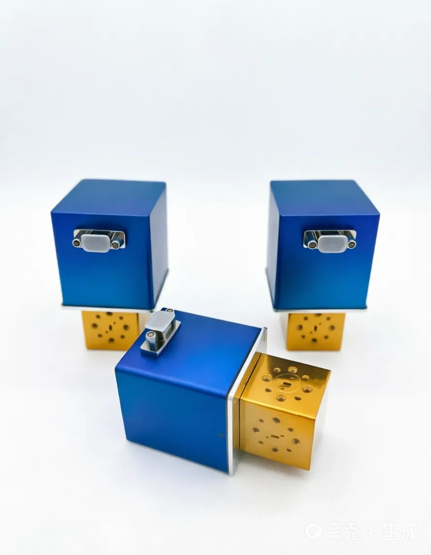
How Do You Choose a Waveguide Switch When the Datasheets All Look Alike?
A waveguide switch moves an RF path from one port to another inside a hollow metal guide. The job sounds simple, and that is exactly why the choice goes wrong. Two switches with the same three-port drawing and the same "0.1 dB" headline can behave nothing alike in your system once frequency, power, and the failure mode show up. This guide walks the five decisions that separate a switch you forget about from one that takes the link down.
Start With the RF Path, Not the Catalog
The first filter is mechanical, not electrical. Your switch has to match the WR size of the waveguide it sits in, because that size is set by the operating band, not by preference. A mismatch at the flange is not a tuning problem, it is a reflection problem, and it shows up as lost power and a stressed source.
We build electromechanical and manual switches across WR-137 down to WR-10, which covers roughly 5.85 to 110 GHz. If you are not sure which WR belongs to your band, the waveguide size chart maps every standard rectangular guide to its frequency range and inner dimensions. Lock the band and the WR size before you read another line of any datasheet.
SPDT or DPDT: One Path or Two Moving Together
A single-pole double-throw switch has three ports. One input routes to either of two outputs, and it is the right call when only one signal path needs selecting, such as feeding a single transmitter to either a primary or a backup antenna.
A double-pole double-throw transfer switch carries four ports and two paths that move together on one command. Picture a gateway with a main amplifier and a hot standby: the transfer switch puts the main unit on the antenna and the standby on a load, then swaps both when the main unit trips. That is the heart of a redundancy architecture, and it is why we covered the WR-22 DPDT transfer switch as a Q-band survival part rather than a convenience.
| Decision | SPDT | DPDT transfer |
|---|---|---|
| Ports | 3 (one path) | 4 (two paths together) |
| Best for | Select one of two outputs | 1:1 redundancy, main and standby |
| Drawback if forced | Two units needed for two paths | Slightly larger body |
You can imitate a transfer switch by bolting two SPDT units in series, but you also double the flange count in a run where every joint is another place to leak, corrode, or lose a tenth of a decibel. One transfer switch holds the mechanical reference rigid, which matters when phase repeatability across a calibration path is part of the spec.
Latching or Failsafe: What Happens When the Power Dies
This is the decision most people make by accident and then live with for years. A latching switch takes a short pulse of control power to move and then stays put with no holding current. A failsafe switch returns to a spring-loaded default the instant control power disappears, which means it needs continuous current to hold the active state.
The real question is not which is "better." It is what the RF path must be when the cabinet loses power. If losing power must produce a known safe route, such as dropping a transmitter onto a dummy load so a receiver stays protected, choose failsafe. If the last commanded state should be preserved and you would rather not dissipate holding current inside an already warm enclosure, choose latching. Position indicators and a manual override knob are worth ordering either way, because the first field fault you debug will probably be a control cable in the wrong socket.
The Four Numbers That Decide Your Link Budget
| Spec | What it protects | Red flag |
|---|---|---|
| Insertion loss | Forward power reaching the load | Quoted only at mid-band |
| Isolation | Receiver from transmit leakage | Below 40 dB at full power |
| VSWR | Source from reflection | Above 1.25:1 |
| Switching speed | Blind spot during rotation | No mute interlock specified |
Insertion loss is the number engineers quote first and feel last. A switch specified at 0.1 dB loses about 2.3 percent of the forward power as heat in the housing. Run 100 W through it and roughly 2.3 W has to leave as heat, which is why the body needs a real thermal path to the mounting surface. Industry-standard motorized switches in this class are commonly specified at 0.3 dB insertion loss and 60 dB isolation, so a 0.1 dB figure hands margin back to a link already fighting rain fade.
Isolation is what protects your receiver. Feed 100 W, or 50 dBm, into a switch with 50 dB isolation and the isolated port sees about 1 mW, or 0 dBm, which a low-noise amplifier shrugs off. Drop that to 30 dB and the same port sees 100 mW, which is enough to end the conversation.
VSWR of 1.20 equals 20.8 dB return loss, about 0.8 percent of the incident wave reflecting back toward your amplifier. At 1.25:1 you are at 19.1 dB and 1.2 percent. That gap stops looking slight when the reflected wave has to survive the isolator on the way back to a device that costs more than the switch.
Switching speed sets the blind spot. A typical electromechanical switch moves in about 60 ms, and during that rotation the rotor is physically between ports. Every switch in this family must be muted before it moves, because switching while RF is live is what arcs and carbonizes the cavity.
Power Handling: Average, Peak, and Duty Cycle
Waveguide switches earn their keep at high average power, where the signal travels through air instead of a center conductor and the heat spreads across the whole inner surface. The number that trips people up is the pulse: a 1 kW peak at 5 percent duty is only 50 W of average heating, yet the peak still has to survive the voltage. Size the switch against the average you actually dissipate, then confirm the peak and the pulse width against the switching limit. Never let a quoted average hide a peak the cavity cannot take.
Flange, Indicator, and Override: The Details That Bite Later
The flange is where two companies' drawings meet. Confirm the UG number, cover versus grooved style, dowel pin holes, and cover depth before you order, because the same flange series is not the same thing as aligned pins and the right depth. A part that looks interchangeable on paper can sit a millimeter proud and wreck the interface.
Position indicators matter the moment the switch is out of sight. Dry-contact micro-switches tell your controller which port is live, and they turn a silent fault into a logged one. A manual override knob lets a technician move the rotor by hand during a power loss or an actuator fault, which is the difference between a ten-minute fix and a truck roll.
At AO Microwave every electromechanical switch can be built with these options, and custom bands or flanges are a quotation, not a project. Every inquiry gets a firm quote with a full datasheet inside 24 hours.
A Six-Step Selection Checklist
1. Lock the operating band and the matching WR size first.
2. Pick SPDT or DPDT from whether one path or two must move together.
3. Decide latching or failsafe from what the path must be when power fails.
4. Set insertion loss, isolation, and VSWR from your link margin, not from the catalog minimum.
5. Confirm average power, peak power, and duty cycle with margin.
6. Verify the flange style, position indicators, and a manual override if the site is remote.
Frequently Asked Questions
Q: What WR size do I need for a given frequency?
A: The WR size is fixed by the operating band, not by choice. Each standard rectangular guide covers a frequency window, and the waveguide size chart lists every WR from WR-137 to WR-10 with its range and inner dimensions. Match the band first, then everything else.
Q: Is a DPDT switch just two SPDT switches?
A: Electrically it can imitate two SPDT paths, but mechanically it is one rotor moving two channels together. Stacking two SPDT units doubles the flange count and the leak paths, while a single transfer switch holds the alignment rigid. For 1:1 redundancy, the transfer switch is the cleaner build.
Q: Can I switch a waveguide switch while RF is running?
A: No. Switching under live RF is called hot switching, and as the rotor turns the air gap opens and the voltage breaks down into an arc that carbonizes the cavity. Always mute or turn off the RF source for the brief rotation window before you command a change.
Q: How long do electromechanical waveguide switches last?
A: Built and driven within their voltage and environment limits, the latching styles are rated for more than one million mechanical cycles. Life drops sharply if you hot-switch or drive them outside the specified control range, so the rating assumes cold switching.
Q: Do I need position indicators on every switch?
A: Not every one, but any switch that sits inside a cabinet or a remote site should have them. Dry-contact indicators let your controller confirm the active port and log a fault instead of letting a silent misalignment take the link down.
Q: What does a custom waveguide switch cost and how long does it take?
A: Stocked standard models ship in a few working days, standard configurations run three to four weeks, and custom bands or flanges take four to eight weeks depending on complexity. There is no minimum order on standard models, and the quote with a full datasheet arrives within 24 hours.
Ready to Spec Your Waveguide Switch?
Send us your band, configuration, and control interface. We will confirm the flange, the actuator, and the lead time, and return a full datasheet within 24 hours.
Contact Our Engineering Team