
How Waveguide Rotary Joints Maintain Stable RF Performance During Antenna Rotation
Waveguide rotary joints maintain stable RF during rotation: choke joint physics, VSWR WOW vs static specs, silver plating, Ku-band WR51, lifetime and altitude derating. Selection guide with case study
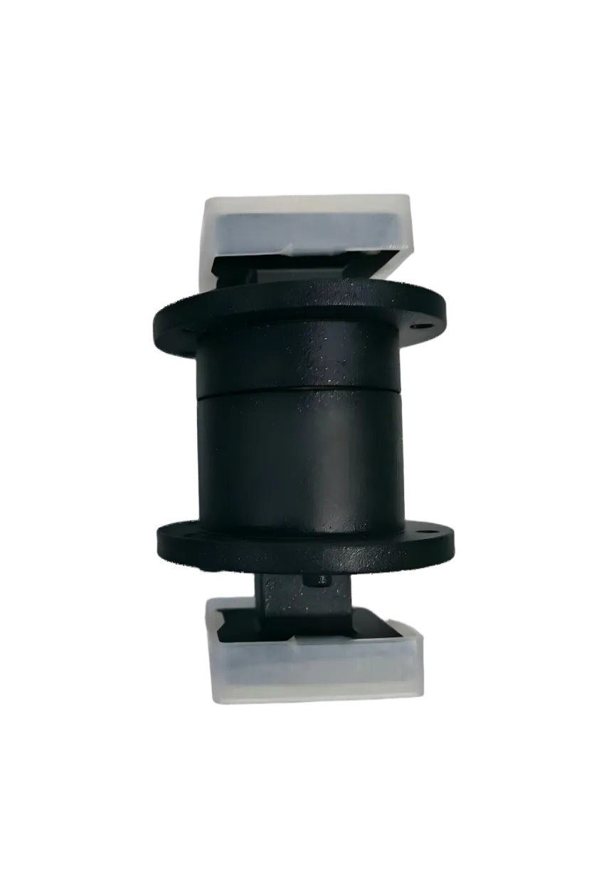
How Waveguide Rotary Joints Maintain Stable RF Performance During Antenna Rotation
A waveguide is a rigid metal tube. An antenna must rotate, often continuously, to scan the sky. Connecting one to the other without tearing the metal apart requires a component that does two contradictory things at once: maintain a mechanically continuous RF path while physically separating into two independently moving parts. This is the waveguide rotary joint—and understanding how it achieves this reveals why its specifications are unlike any other waveguide component in the RF chain.
In a fixed waveguide run, insertion loss and VSWR are single-number values measured once. In a rotary joint, those numbers change with every degree of rotation. The real specification is not the static value on the datasheet—it is the variation of that value across a full 360° sweep, captured in a parameter called WOW (variation with rotation). This article explains the physics of rotary joints, why WOW is the most underrated specification in the datasheet, and what the engineering choices—choke joint design, silver plating, aluminum housing, flange selection—mean for real-world system performance.
The Choke Joint: Making Electrical Contact Without Mechanical Contact
A rotary joint is not a slip ring. Slip rings use physical metal-to-metal contacts to pass current; at microwave frequencies, any mechanical contact becomes a nonlinear junction—a source of intermodulation, micro-arcing, and unpredictable impedance. The waveguide rotary joint solves this with a choke joint: two concentric waveguide sections separated by a precisely dimensioned air gap that acts as an RF short circuit, not a break.
The choke joint is a quarter-wavelength (λ/4) transformer in the radial direction. One side of the joint terminates in a groove cut to a depth of λ/4 at the operating frequency. This groove transforms the open end of the gap into a short circuit at the waveguide wall boundary. The RF signal sees a continuous metal wall even though the two mechanical parts are physically separated by a gap large enough to allow free rotation—typically 0.1 mm to 0.5 mm. No contact, no wear debris, no intermodulation. Just a perfectly tuned microwave cavity that happens to spin.
The WOW Specification: Why Variation Matters More Than the Static Value
Every rotary joint datasheet lists VSWR and insertion loss. The better ones also list VSWR WOW and Insertion Loss WOW—the peak-to-peak variation of these parameters as the joint completes one full 360° rotation. And here is the uncomfortable reality: in system design, WOW often matters more than the absolute value.
| Parameter | What It Means | Why It Matters |
|---|---|---|
| VSWR (static) | Worst-case reflection at any single angular position | Sets the minimum return loss the transmitter must tolerate |
| VSWR WOW | Cyclic variation of reflection as the antenna rotates | Creates periodic amplitude modulation on the received signal—a source of false targets in radar, bit errors in data links |
| Insertion Loss (static) | Worst-case loss at any single angular position | Determines link budget margin |
| Insertion Loss WOW | Cyclic variation of loss with rotation | Modulates signal amplitude; looks like antenna pattern ripple to the receiver, making it indistinguishable from actual target scintillation |
Consider a radar system with a rotary joint specified at VSWR WOW = 0.1 and IL WOW = 0.1 dB. At an S-band search radar rotating at 6 rpm, this produces a barely perceptible modulation at 0.1 Hz—well below any Doppler filter cutoff. At an X-band fire-control radar rotating at 60 rpm, the same WOW creates a 1 Hz modulation that falls squarely in the clutter rejection band. The WOW value itself is not the problem—the problem is specifying a rotary joint without knowing at what rotation rate the system must operate, and whether the resulting modulation frequency interacts with downstream signal processing.
Why Silver Plating Is Not a Cosmetic Choice
The interior of a quality waveguide rotary joint is silver-plated—not gold, not nickel, not left as bare aluminum. The reasoning is rooted in conductivity, not corrosion resistance alone.
Silver has the highest electrical conductivity of any metal: 6.3 × 10⁷ S/m, roughly 6% higher than copper and 40% higher than gold. In a rotary joint, the RF current flows along the choke groove walls, the circular waveguide walls, and the transitions. Every surface in the current path contributes to ohmic loss. At Ku-band (15.7–17.3 GHz), skin depth in silver is approximately 0.5 μm at 16.5 GHz—meaning only the outermost half-micron of plating carries the RF current.
Gold is sometimes specified for rotary joints used in corrosive environments, but it comes at a penalty: 40% higher resistivity means higher insertion loss, and gold's hardness makes it susceptible to micro-cracking under the thermal cycling that rotary joints experience in outdoor installations. Silver, properly passivated against tarnish, offers the best combination of conductivity, mechanical compliance, and corrosion resistance for rotary joint interiors.
Aluminum is chosen for the housing for a different reason: weight. A rotary joint mounts between the fixed waveguide run and the rotating antenna pedestal. Every gram of mass on the rotating side increases bearing load, motor torque requirement, and mechanical wear. Aluminum's density (2.7 g/cm³ vs. 8.9 g/cm³ for brass) and excellent machinability make it the default choice for airborne and shipboard rotary joints, where weight translates directly into fuel consumption and structural reinforcement cost.
Environmental Ruggedization: When the Spec Sheet Meets the Real World
A rotary joint rated for -40°C to +71°C operation, 35,000-foot altitude, 30 g shock, and 95% humidity is not over-engineered. It is designed for the operational envelope that radar and satellite systems actually encounter.
The aluminum housing expands and contracts with temperature. At -40°C, the choke gap shrinks by roughly 20–30 μm compared to its room-temperature dimension due to the coefficient of thermal expansion (CTE) of aluminum (~23 × 10−6/°C over a 65°C delta on a 50 mm diameter). If the gap was machined to the minimum acceptable value at 25°C, that 20 μm closure at -40°C can bring the rotating section close enough to the stationary section to risk physical contact—which creates galling, wear particles, and a rapid degradation cascade.
At the opposite extreme—+71°C with 95% humidity—condensation forms on internal surfaces during temperature transitions. Silver plating resists corrosion better than bare copper or brass, but only if the plating is continuous and pore-free. A single pinhole in the silver layer over aluminum creates a galvanic couple: the silver (cathode) protects itself while the aluminum (anode) corrodes underneath, eventually causing the silver to delaminate in flakes that bridge the choke gap.
The altitude rating (35,000 feet, or roughly 10.7 km) addresses pressure reduction. At 10.7 km, atmospheric pressure is approximately 25% of sea level. The breakdown voltage of air drops proportionally. A rotary joint that handles 1 kW peak at sea level must be verified to handle it at the rated altitude—or the system must pressurize the waveguide run. For airborne applications, the altitude rating is not optional; it is the primary safety margin.
WR51 Ku-Band Rotary Joint: A Case Study in Specification
The following specifications represent a real customized WR51 waveguide rotary joint designed for the 15.7–17.3 GHz band. Each number carries a systems-engineering story.
| WR51 Waveguide Rotary Joint Specifications | |
|---|---|
| Frequency Range | 15.7 – 17.3 GHz |
| VSWR (max) | 1.50 |
| VSWR WOW | 0.10 |
| Insertion Loss (max) | 0.50 dB |
| Insertion Loss WOW | 0.10 dB |
| Power Handling | 100 W CW / 1 kW Peak |
| Rotation | 360°, 10 rpm |
| Rotational Life | 20,000,000 rotations |
| Flange | FBP180 (cover) |
| Materials | Aluminum housing, silver-plated interior, black anti-corrosion paint exterior |
| Operating Temperature | -40°C to +71°C |
| Altitude | 35,000 ft (design-assured) |
| Shock / Vibration | 30 g, 11 ms / Random vibration compliant |
| Humidity | 95% |
Why 10 rpm? The rotation speed rating is not arbitrary. A ground-based tracking radar following a low-earth-orbit satellite at 550 km altitude traverses roughly 1° of sky per second at zenith, or 0.17 rpm. A shipboard navigation radar antenna rotates at 24–30 rpm. A fighter aircraft radar antenna scans sector-to-sector at the equivalent of 60–100 rpm when slewing. The 10 rpm rating places this rotary joint in the domain of ground-based tracking radars, fixed SATCOM terminals with limited scanning, and microwave test platforms—applications where rotation is slow but angular precision and long-term stability dominate the requirements.
Why 20 million rotations? At 10 rpm continuous operation, 20 million rotations is approximately 3.8 years of 24/7 service. In a typical tracking radar operating 12 hours per day, this translates to over 7 years of field life. This is not the theoretical maximum of the choke joint (which can exceed 100 million cycles in controlled environments)—it is the rated life at which electrical specifications remain guaranteed. Beyond 20 million rotations, WOW increases, insertion loss drifts, and performance degrades within a predictable envelope.
Why FBP180 flange? The FBP series is part of the EIA cover flange family for rectangular waveguide. Specifying the flange type at the RFQ stage eliminates the most common integration error: ordering a rotary joint with incompatible flanges and discovering the mismatch only during installation. The Standard Waveguide Flange Cross-Reference Table maps EIA and IEC designations side by side—a five-second check that saves weeks of rework.
System Integration: What Goes Around the Rotary Joint
The rotary joint does not exist in isolation. On the fixed side, rigid waveguide feeds into the stationary port. On the rotating side, the output connects to the antenna feed—often through additional waveguide bends, twists, or flexible sections that absorb the mechanical misalignment between the rotary joint's axis and the antenna's mounting geometry.
A common failure mode in the field is transmitting bending stress from the waveguide run directly into the rotary joint housing. The rotary joint is designed to handle its own internal rotation—not to serve as a structural support for the waveguide hanging off its flanges. A short flexible twistable waveguide section on each port decouples the rotary joint mechanically from the rest of the waveguide run. This is a $200 part that protects a $2,000–$5,000 rotary joint from stress-induced bearing wear and choke gap deformation.
When the RF chain transitions from waveguide to coaxial for connection to solid-state amplifiers or LNAs, a waveguide to coaxial adapter provides the interface. The adapter's flange must match the rotary joint's flange family. An FBP flanged rotary joint paired with a UBR flanged adapter creates an interference that no gasket bridges—and at Ku-band frequencies, the resulting gap concentrates enough electric field to arc at power levels far below the rated peak power of either component individually.
Frequently Asked Questions
Q: What is the difference between an I-type, L-type, and U-type rotary joint?
These designations refer to the physical orientation of the waveguide ports relative to the rotation axis. An I-type rotary joint has both ports aligned along the rotation axis—the RF enters and exits in a straight line. An L-type has one port perpendicular to the rotation axis. A U-type has both ports perpendicular to the axis, forming a U-shaped RF path. The choice depends on the mechanical layout of the antenna pedestal and the available space around the rotation bearing. U-type is the most common for radar pedestal installations because it places both waveguide connections on the same side, simplifying cable management.
Q: What does VSWR WOW of 0.1 actually mean in practice?
It means that as the rotary joint rotates through a full 360°, the VSWR varies between its minimum and maximum values, and the difference between those extremes is no more than 0.1. If the static VSWR is 1.50, the VSWR at any angular position falls between 1.40 and 1.50. The system impact is a received signal amplitude modulation equal to 20 × log10((VSWRmax − 1)/(VSWRmin − 1)). For a 0.1 WOW at VSWR 1.50/1.40, this is approximately 1.9 dB of peak-to-peak amplitude ripple—sufficient to produce false targets in high-sensitivity radar if not accounted for in the signal processing chain.
Q: Why not use a coaxial rotary joint instead of a waveguide one?
Coaxial rotary joints are viable below 18 GHz and offer simpler mechanical design. However, they use physical sliding contacts (beryllium-copper spring fingers against a gold-plated rotor) that wear over time, generate intermodulation products, and have higher insertion loss at Ku-band and above (>0.5–1.0 dB typical vs. <0.5 dB for waveguide). For high-power applications above 100 W, the current density at the contact points causes localized heating and accelerated wear. For systems requiring lowest possible loss, highest power handling, or maximum intermodulation-free dynamic range, waveguide choke-joint rotary joints are the preferred approach.
Q: How do I specify a rotary joint's rotational life requirement?
Calculate: (rotation speed in rpm) × (60 minutes) × (operating hours per day) × (365 days) × (required service years). A 10 rpm radar operating 12 hours per day for 10 years needs 10 × 60 × 12 × 365 × 10 = 26.3 million rotations. Always add a 50% margin. In this case, specify a minimum of 40 million rotations. Also clarify whether the rating is at the guaranteed electrical performance level or at end-of-life (where specs may be degraded). Many manufacturers rate life as "mechanical only"—the joint still rotates but may have exceeded its VSWR and IL specifications.
Q: Does a waveguide rotary joint need maintenance?
Choke-joint waveguide rotary joints are inherently low-maintenance because there is no physical contact in the RF path. The primary maintenance concerns are the mechanical bearings, not the RF performance. Bearings should be inspected per the manufacturer's recommended interval—typically every 2–5 years for ground-based installations, more frequently for shipboard installations where salt spray accelerates corrosion. If the choke gap becomes contaminated with debris, a qualified technician can disassemble, clean with isopropyl alcohol, and reassemble the unit. However, the choke gap is a precision-machined feature; field disassembly by untrained personnel risks introducing misalignment that degrades WOW performance.
Q: Can one rotary joint cover multiple frequency bands?
A single-channel choke-joint rotary joint is inherently narrowband: the λ/4 choke groove is tuned to a specific center frequency, and the circular waveguide must operate in a single E01 mode without exciting higher-order modes. Bandwidth is typically 5–10% of center frequency. Multi-band operation requires either a multi-channel rotary joint (separate concentric RF channels, each tuned to a different band) or accepting degraded VSWR and insertion loss at the band edges. A rotary joint specified for 15.7–17.3 GHz (approximately 10% bandwidth) can cover that band with a single choke design. Attempting to cover both Ku-band (12–18 GHz) and K-band (18–27 GHz) with a single-channel rotary joint would result in unacceptably high WOW and insertion loss at the band edges.
Market Context
The global high-frequency waveguide rotary joint market was valued at USD 392 million in 2024 and is projected to reach USD 649 million by 2032 (PW Consulting, 2026). Military radar systems account for 45% of demand, satellite communications 27%. The rapid deployment of LEO satellite constellations—with over 50,000 authorized satellites—is driving demand for Ku-band and Ka-band rotary joints in ground station tracking antennas. North America holds 36% of the market, Asia Pacific 30%, and Europe 25%. As phased-array antennas reduce the need for mechanical rotation in some applications, the remaining rotary joint installations skew toward higher-performance, longer-life units where the cost of a premature replacement—including tower access, recalibration, and downtime—exceeds the rotary joint's purchase price by a factor of ten or more.
AO Microwave: Custom Rotary Joints Engineered to Your System
We design and manufacture waveguide rotary joints across all standard waveguide sizes from WR-284 to WR-28. Every unit ships with full swept S-parameter data and WOW measurements across 360° of rotation at 1° increments—not just the two data points on a datasheet. Custom flange configurations, extended temperature ranges, pressurization ports, and multi-channel designs are standard capabilities. Engineering support from first concept through field deployment. No minimum order.
Need a Custom Waveguide Rotary Joint?
Tell us your frequency band, power level, rotation speed, and environmental requirements. We will provide a technical proposal with WOW guarantees at your operating conditions.
Request Engineering Review