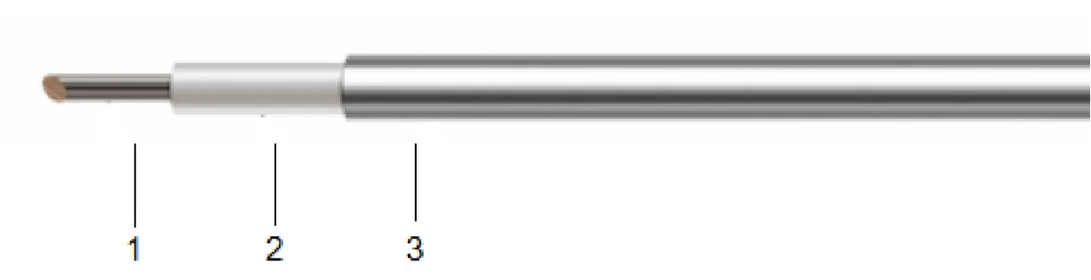
CK Series: Low Loss & Amplitude Stable Semi-Rigid Coaxial Cable
When flexible cables fail in dense RF instruments and phased arrays, CK Series semi-rigid cable delivers. Seamless copper tube achieves 165 dB shielding regardless of packing density. PTFE dielectric at 81% Vp with <750 PPM phase stability. CK086: 40 GHz in 2.18 mm OD, 7 mm bend radius. CK141: lower loss and 4x power to 26.5 GHz. Pre-formed, connectorized, VNA-verified assemblies. Contact sales@aomicrowave.com for your routing requirements.
CK Series: Low Loss & Amplitude Stable Semi-Rigid Coaxial Cable
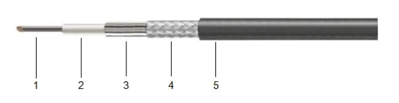
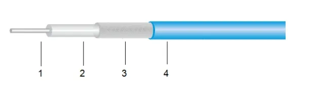
When your RF design demands absolute signal integrity in the most confined spaces -- inside densely packed instruments, phased array feed networks, or satellite payload modules -- flexible cables introduce unacceptable variables: bending radius takes up real space, shielding degrades over flex cycles, and phase stability shifts with every cable movement. The CK Series semi-rigid coaxial cable eliminates these compromises. A seamless copper tube outer conductor and solid PTFE dielectric core deliver 165 dB shielding effectiveness, 81% velocity of propagation, and phase stability better than 750 PPM across temperature excursions -- the kind of repeatable, trustworthy performance that precision RF instruments and aerospace systems depend on.
Core Technology Highlights
Seamless Copper Tube Outer Conductor
No braid gaps. No foil overlaps. The solid-drawn seamless copper tube with tri-metal plating provides a continuous cylindrical shield achieving 165 dB shielding effectiveness -- isolating your signal from co-located transmitters in dense RF environments where flexible cable shielding simply cannot keep up.
PTFE Dielectric, 81% Propagation Velocity
Solid PTFE core delivers best-in-class 81% Vp with tightly controlled impedance. Attenuation as low as 30.80 dB/100m at 1 GHz (CK141). The result: shorter electrical delays, lower insertion loss, and phase-matched multi-channel runs that stay locked across temperature.
40 GHz Capability in 2.18 mm OD
CK086 operates clean to 40 GHz in a cable body just 2.18 mm in diameter -- smaller than a 2.4 mm connector barrel. Bend it to a 7 mm radius, form it to your chassis routing, and get lab-grade RF performance where no flexible cable would fit.
Phase Stable Across Temperature Extremes
<750 PPM phase change over -55 C to +85 C means your phased array calibration holds. With an operating range spanning -55 C to +250 C, CK Series cables survive reflow soldering, thermal vacuum cycling, and the harshest qualification profiles without degradation.
CK Series Parameter Table

Which CK Cable Fits Your Project? Start Here.
Two models. Two frequency bands. Answer the questions below to identify the right semi-rigid cable for your interconnect.
What is your maximum operating frequency?
How tight is your available routing space?
What matters most -- loss, power, or formability?
Tightest space, highest frequency (to 40 GHz) -> CK086 | Lowest loss, highest power -> CK141
Both models: 50 Ohm, 81% Vp, 165 dB shielding, -55 C to +250 C, tri-metal plated seamless copper tube.
Problems CK Series Solves
Flexible Cables Degrade in Dense RF Environments
Braided shields develop gaps under flexing, leaking signals between adjacent channels. CK Series seamless copper tube delivers 165 dB shielding that does not degrade with handling -- eliminating cross-talk in tightly packed instrument chassis and phased array feed networks.
Phase Drift During Thermal Cycling
PTFE dielectric expansion in flexible cables causes phase errors that shift with every temperature change. CK Series phase stability <750 PPM over -55 C to +85 C means your phased array beam pattern stays calibrated through thermal cycles -- no recalibration mid-mission.
No Room for Cable Bending Radius
Flexible cables need generous bend radii (often 10x OD) that consume chassis volume. CK086 bends to 7 mm -- a 3.2:1 radius-to-OD ratio. Route RF literally around corners in spaces where flexible assemblies would kink and fail.
Connector Attachment Reliability on Rigid Lines
Semi-rigid cable demands precision connector soldering. We build, solder, and VNA-verify every CK Series assembly in-house. SMA, 2.92 mm (K), 3.5 mm, and custom connectors all available -- one vendor, one test report, zero finger-pointing.
Where CK Cables Are Used
VNA & RF Test Instrumentation
CK086's 40 GHz bandwidth, 7 mm bend radius, and phase stability make it the go-to choice for internal VNA port cabling where calibration accuracy is non-negotiable.
Phased Array Radar Feed Networks
Multi-channel phase matching across dozens of CK086 or CK141 assemblies. <750 PPM phase stability keeps beam steering accurate through temperature swings in airborne and naval platforms.
Satellite Payload & Space-Qualified Modules
-55 C to +250 C operating range, solid-drawn seamless copper, PTFE dielectric -- materials and construction proven through thermal vacuum cycling and radiation exposure.
Semiconductor ATE & Probe Station Wiring
CK086 routes RF stimulus and measurement signals through tight probe card assemblies. 165 dB shielding prevents digital noise from coupling into sensitive RF measurements.
Military Avionics & EW Systems
CK141 handles transmit power levels in jammer and radar exciter modules. Seamless copper construction survives gunfire vibration and rapid decompression without shield degradation.
Microwave Point-to-Point Radio
ODU-to-antenna jumpers in 6-38 GHz links. CK141's low loss preserves link budget; CK086's small OD fits compact ODU enclosures. Custom formed to your mechanical CAD.
Frequently Asked Questions
Q: What does "semi-rigid" mean, and when should I choose it over flexible cable?
Semi-rigid cable uses a solid-drawn seamless copper tube as the outer conductor instead of a braided shield. This gives you three critical advantages: (1) 165 dB shielding that does not degrade with handling, (2) superior phase stability because the rigid tube constrains dielectric expansion, and (3) much tighter bend radii relative to cable OD. Choose semi-rigid when your installation is permanent (form once, install once) and you need the best possible RF performance. If your application requires repeated flexing or frequent reconfiguration, consider our CJ Series flexible cables.
Q: Why does CK086 reach 40 GHz while CK141 stops at 26.5 GHz?
This is dictated by higher-order mode cutoff. As cable diameter increases, the TE11 mode onset frequency decreases. CK141's 3.00 mm dielectric diameter shifts the first higher-order mode below 26.5 GHz. CK086's smaller 1.68 mm dielectric pushes TE11 cutoff well above 40 GHz, guaranteeing pure TEM propagation across its entire rated band. For applications above 26.5 GHz, CK086 is the correct choice.
Q: Is 165 dB shielding overkill for my application?
"Overkill" depends on your RF environment density. In a single-instrument test setup, 70-90 dB may suffice. But in a phased array with 64 channels packed into a 300 mm chassis, or a satellite payload where RX and TX modules sit millimeters apart, 165 dB is the difference between a clean beam pattern and cross-talk-induced sidelobes. CK Series shielding comes from a continuous copper tube -- there are no braid gaps to leak through, regardless of how tight your packing density.
Q: Can you pre-form CK cables to my mechanical drawing?
Yes. Send us your 3D CAD or 2D mechanical drawing with bend locations, angles, and connector types. We form, solder connectors, and VNA-test every assembly before shipping. You receive a drop-in RF interconnect -- no bending jigs, no soldering station, no post-assembly tuning required.
Q: How do I estimate loss for my specific cable length and frequency?
Scale linearly from the attenuation table. Example: a 200 mm CK086 jumper at 10 GHz -> 176.20 dB/100m x 0.2 = 0.35 dB. For frequencies between table entries, linear interpolation works well. For precise S-parameter data at your exact frequency and length, contact us with your requirements and we will provide a custom link budget analysis.
Q: Which connectors are available for CK Series assemblies?
SMA (to 18 GHz), 3.5 mm (to 26.5 GHz), and 2.92 mm / K-type (to 40 GHz) are standard. N-type and TNC also available on CK141. All connectors are precision soldered to the semi-rigid cable body and verified on a calibrated VNA. Custom connector combinations and right-angle configurations available on request.
Tell Us Your Setup -- We'll Recommend the Right CK Cable
Share your operating frequency, routing constraints, connector preferences, and whether you need pre-formed assemblies. Our engineering team will get back to you with a recommendation and quote -- no obligation.
Contact Us: sales@aomicrowave.com