CSF Series: Semi-Flexible Coaxial Cable
CSF Series semi-flexible coaxial cables solve dense interconnect challenges in phased array radar and ECM systems. OD from 1.19 mm (CSF047) to 6.85 mm (CSF250FEP). 100 dB shielding eliminates co-site interference. Silver-plated copper clad steel center conductor, PTFE dielectric, 40 GHz (CSF047/CSF086), 50 Ohm, 70% Vp. Hand-formable, 4 mm static bend radius. Unjacketed and FEP-jacketed variants with identical RF performance. -65 to +150 deg C. 500 to 3500 V DC withstand.
CSF Series: Semi-Flexible Coaxial Cable for High-Frequency Defense & Radar Interconnects
When your system demands uncompromising RF performance in phased array radar or electronic warfare platforms, the cable must deliver low loss at millimeter-wave frequencies while maintaining perfect shielding integrity in dense signal environments. The CSF Series from AO Microwave solves this with a proprietary semi-flexible construction — silver-plated copper clad steel center conductor, precision PTFE dielectric, and 100 dB shielding effectiveness — giving you the mechanical formability of semi-rigid with the installation forgiveness your field teams need.
Core Technology Highlights
40 GHz Capability in Ultra-Thin Form Factor
The CSF047 and CSF086 models operate to 40 GHz — critical for Ka-band phased array element interconnects. With outer diameters as small as 1.19 mm (CSF047), you can pack dense feed networks without sacrificing phase-matched performance. Silver-plated copper clad steel center conductor ensures excellent conductivity with the strength needed for semi-flexible forming.
100 dB Shielding — No Signal Leakage, No Interference
Tin overcoated copper wire braiding achieves 100 dB shielding effectiveness across the entire frequency range. In ECM systems where multiple high-power emitters and sensitive receivers operate in close proximity, this level of isolation prevents cross-talk that would otherwise degrade system sensitivity or cause false targeting.
Semi-Flexible: Bend Once, Perform Forever
Unlike rigid semi-rigid cables that require precision tube bending tools, CSF Series cables can be hand-formed to routing paths and retain their shape permanently. Static bend radii as low as 4 mm (CSF047) mean you can route around chassis obstacles without the risk of dielectric kinking or impedance discontinuities that plague fully flexible alternatives.
FEP Jacket Option for Environmental Hardening
Every CSF model is available with an FEP outer jacket (CSF047FEP through CSF250FEP). The FEP layer adds abrasion resistance, chemical protection, and an additional dielectric barrier — all without altering the core RF performance. Same attenuation, same Vp, same impedance. Choose jacketed for field-deployed systems, unjacketed for controlled lab environments.
CSF Series Parameter Tables
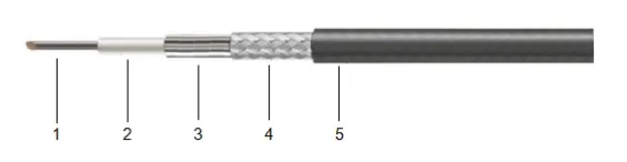
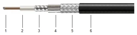
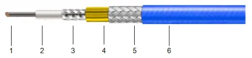
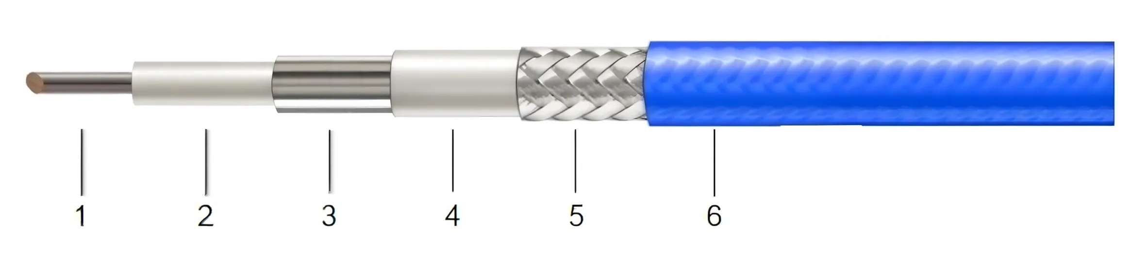
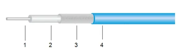
Cable Construction
| Item | Description | Material | CSF047 (mm) |
CSF047FEP (mm) |
CSF086 (mm) |
CSF086FEP (mm) |
CSF141 (mm) |
CSF141FEP (mm) |
CSF250 (mm) |
CSF250FEP (mm) |
|---|---|---|---|---|---|---|---|---|---|---|
| 1 | Center Conductor | Silver-Plated Copper Clad Steel | 0.30 | 0.30 | 0.53 | 0.53 | 0.94 | 0.94 | 1.65 | 1.65 |
| 2 | Dielectric | PTFE | 0.94 | 0.94 | 1.68 | 1.68 | 2.98 | 2.98 | 5.20 | 5.20 |
| 3 | Outer Conductor | Tin Overcoated Copper Wire Braiding | 1.19 | 1.19 | 2.17 | 2.17 | 3.50 | 3.50 | 6.25 | 6.25 |
| 4 | Jacket | FEP | — | 1.60 | — | 2.60 | — | 4.10 | — | 6.85 |
Electrical & Mechanical Specifications
| Item | Description | CSF047 | CSF047FEP | CSF086 | CSF086FEP | CSF141 | CSF141FEP | CSF250 | CSF250FEP |
|---|---|---|---|---|---|---|---|---|---|
| 1 | Frequency (GHz) | 40 | 40 | 40 | 40 | 26.5 | 26.5 | 18 | 18 |
| 2 | Impedance (Ohms) | 50 | 50 | 50 | 50 | 50 | 50 | 50 | 50 |
| 3 | Velocity of Propagation | 70% | 70% | 70% | 70% | 70% | 70% | 70% | 70% |
| 4 | Voltage Withstand (V, DC) | 500 | 500 | 500 | 500 | 1000 | 1000 | 3500 | 3500 |
| 5 | Shielding Effectiveness (dB) | 100 | 100 | 100 | 100 | 100 | 100 | 100 | 100 |
| 6 | Static Bending Radius (mm) | 4 | 4 | 6 | 6 | 8 | 8 | 30 | 30 |
| 7 | Dynamic Bending Radius (mm) | 20 | 20 | 20 | 20 | 40 | 40 | 120 | 120 |
| 8 | Weight (g/m) | 6.6 | 7.9 | 16 | 19 | 41 | 48 | 127 | 127 |
| 9 | Operating Temperature (°C) | -65~+150 | -65~+150 | -65~+150 | -65~+150 | -65~+150 | -65~+150 | -65~+150 | -65~+150 |
Attenuation (Typical @ 25°C) — dB/100 m
| Freq (MHz) | 500 | 1000 | 2000 | 3000 | 5000 | 6000 | 8000 | 10000 | 15000 | 18000 | 20000 | 26500 | 40000 |
|---|---|---|---|---|---|---|---|---|---|---|---|---|---|
| CSF047 | 98.00 | 123.00 | 176.00 | 218.00 | 296.00 | 315.00 | 383.00 | 431.00 | 543.00 | 603.00 | 642.00 | 759.00 | 975.00 |
| CSF047FEP | 98.00 | 123.00 | 176.00 | 218.00 | 296.00 | 315.00 | 383.00 | 431.00 | 543.00 | 603.00 | 642.00 | 759.00 | 975.00 |
| CSF086 | 47.00 | 68.00 | 100.00 | 124.00 | 167.00 | 182.00 | 215.00 | 245.00 | 312.00 | 351.00 | 373.00 | 445.00 | 587.00 |
| CSF086FEP | 47.00 | 68.00 | 100.00 | 124.00 | 167.00 | 182.00 | 215.00 | 245.00 | 312.00 | 351.00 | 373.00 | 445.00 | 587.00 |
| CSF141 | 27.00 | 41.00 | 61.00 | 78.00 | 105.00 | 115.00 | 139.00 | 158.00 | 200.00 | 222.00 | 245.00 | 297.00 | — |
| CSF141FEP | 27.00 | 41.00 | 61.00 | 78.00 | 105.00 | 115.00 | 139.00 | 158.00 | 200.00 | 222.00 | 245.00 | 297.00 | — |
| CSF250 | 16.00 | 24.00 | 37.00 | 48.00 | 65.00 | 71.00 | 87.00 | 99.00 | 127.00 | — | — | — | — |
| CSF250FEP | 16.00 | 24.00 | 37.00 | 48.00 | 65.00 | 71.00 | 87.00 | 99.00 | 127.00 | — | — | — | — |
Power Handling (Typical @ 40°C) — kW/100 m
| Freq (MHz) | 500 | 1000 | 2000 | 3000 | 5000 | 6000 | 8000 | 10000 | 15000 | 18000 | 20000 | 26500 | 40000 |
|---|---|---|---|---|---|---|---|---|---|---|---|---|---|
| CSF047 | 0.0460 | 0.0367 | 0.0256 | 0.0207 | 0.0152 | 0.0143 | 0.0118 | 0.0105 | 0.0083 | 0.0075 | 0.0070 | 0.0059 | 0.0046 |
| CSF047FEP | 0.0460 | 0.0367 | 0.0256 | 0.0207 | 0.0152 | 0.0143 | 0.0118 | 0.0105 | 0.0083 | 0.0075 | 0.0070 | 0.0059 | 0.0046 |
| CSF086 | 0.3380 | 0.2190 | 0.1420 | 0.1100 | 0.0800 | 0.0600 | 0.0594 | 0.0520 | 0.0404 | 0.0360 | 0.0338 | 0.0270 | 0.0250 |
| CSF086FEP | 0.3380 | 0.2190 | 0.1420 | 0.1100 | 0.0800 | 0.0600 | 0.0594 | 0.0520 | 0.0404 | 0.0360 | 0.0338 | 0.0270 | 0.0250 |
| CSF141 | 0.6010 | 0.4250 | 0.3000 | 0.2450 | 0.1900 | 0.1730 | 0.1500 | 0.1340 | 0.1090 | 0.1000 | 0.0950 | 0.0820 | — |
| CSF141FEP | 0.6010 | 0.4250 | 0.3000 | 0.2450 | 0.1900 | 0.1730 | 0.1500 | 0.1340 | 0.1090 | 0.1000 | 0.0950 | 0.0820 | — |
| CSF250 | 1.8310 | 1.1880 | 0.7710 | 0.5980 | 0.4350 | 0.3882 | 0.3240 | 0.2820 | 0.2190 | 0.1960 | — | — | — |
| CSF250FEP | 1.8310 | 1.1880 | 0.7710 | 0.5980 | 0.4350 | 0.3882 | 0.3240 | 0.2820 | 0.2190 | 0.1960 | — | — | — |
Which CSF Cable Fits Your System? Start Here.
Three decision points narrow the field from eight models to the one that matches your RF chain requirements.
What is your maximum operating frequency?
Ka-band / mmWave — above 26.5 GHz, up to 40 GHz
Only the smallest diameters support clean TEM mode at these frequencies. Choose CSF047 / CSF047FEP or CSF086 / CSF086FEP.
K-band — up to 26.5 GHz
The CSF141 / CSF141FEP offers the best balance of manageable loss and formability in this range.
X/Ku-band — up to 18 GHz
For lowest loss on longer runs, CSF250 / CSF250FEP. 16 dB/100m at 500 MHz is unmatched in the semi-flexible class.
How much space do you have — and how tight is the bend?
Extremely dense — element-level interconnects, TR module feed
4 mm static bend radius, 1.19 mm OD → CSF047 / CSF047FEP. The smallest semi-flexible cable in the AO Microwave portfolio.
Moderate density — subarray feed networks
6–8 mm bend radius options cover most routed scenarios. CSF086 (2.17 mm OD) or CSF141 (3.50 mm OD).
Ample space — bulkhead-to-bulkhead, long equipment runs
30 mm bend radius is generous. CSF250 (6.25 mm OD, 120 mm dynamic bend) for the lowest loss path.
Indoor lab or outdoor field deployment?
Controlled environment — lab bench, ATE rack, thermal chamber
Unjacketed base models (CSF047, CSF086, CSF141, CSF250) save weight and cost. The braid outer conductor is robust enough for handled environments.
Field-deployed — vehicle, shelter, outdoor radar face
FEP jacket variants (CSF047FEP, CSF086FEP, CSF141FEP, CSF250FEP) add abrasion and environmental protection. Same RF performance, field-ready durability.
Mixed deployment — lab qualification then field installation
Jacketed and unjacketed variants share identical dielectrics and conductors. Qualify with unjacketed in the lab, then swap to FEP versions for production units — no re-testing required.
Highest frequency, tightest space → CSF047 | 40 GHz balanced → CSF086 | 26.5 GHz sweet spot → CSF141 | Lowest loss, highest power → CSF250
Add "FEP" to any model = environmental jacket, identical RF performance. All models: 50 Ω, 70% Vp, 100 dB shielding, -65 to +150°C.
Problems CSF Series Solves
Dense Array Packaging Without Phase Errors
Phased array element spacing at Ka-band demands cables smaller than 2 mm OD. CSF047 (1.19 mm) and CSF086 (2.17 mm) fit between adjacent TR modules. The 70% Vp consistency across the series ensures phase-matched cable sets without individual trimming.
Co-Site Interference in ECM Suites
When jamming transmitters and ESM receivers share a platform, cable-to-cable coupling can blind your own receivers. 100 dB shielding effectiveness eliminates this risk — a 30 dB margin over typical single-braid solutions. Your receivers see only what the antenna sees.
Installation Damage from Semi-Rigid Forming
True semi-rigid cables require dedicated bending fixtures and risk dielectric cracking during installation. CSF semi-flexible construction can be hand-formed on-site — no special tools, no kinking, no post-installation VNA surprises. 4 mm static bend radius on CSF047 means you can match the tightest chassis contours.
Temperature Extremes in Airborne & Ground Radar
From -65°C cold-soak at altitude to +150°C near high-power amplifier output stages, CSF Series PTFE dielectric maintains stable electrical characteristics across the full MIL-spec temperature range. No phase drift compensation needed across thermal cycles.
Where CSF Cables Are Deployed
Phased Array Radar
TR module-to-beamformer interconnects. CSF047/CSF086 at 1.19–2.17 mm OD route between densely packed elements. 40 GHz bandwidth supports X through Ka-band arrays. 100 dB shielding isolates transmit and receive paths on shared apertures.
Electronic Countermeasure (ECM)
Jammer output to antenna, DRFM loopback paths. CSF141/CSF250 deliver the power handling for high-ERP jamming while 100 dB shielding prevents self-jamming of co-located ESM receivers. FEP jacket variants for pod-mounted systems.
Satcom Ground Terminals
LNA-to-modem and BUC-to-feed interconnects. CSF086 bridges the frequency gap — 40 GHz ceiling covers Ka-band satcom with headroom. Semi-flexible forming simplifies waveguide-replacement retrofit projects.
Test & Measurement Setups
VNA, spectrum analyzer, and load-pull fixture cabling. Hand-form CSF047/CSF086 directly on the bench for custom DUT interfaces. 70% Vp and stable phase simplify calibration and de-embedding.
Missile Seeker & Fuze RF
Compact, lightweight, and formable for tight radome volumes. CSF047 at 6.6 g/m adds negligible mass. FEP jacket provides environmental sealing. -65°C rating covers high-altitude cold soak.
5G mmWave R&D & OTA Chambers
28 GHz and 39 GHz band characterization setups. CSF086 (40 GHz, 2.17 mm OD) fits chamber feed-through panels and positions with phase-stable repeatability across multiple DUT orientations.
Frequently Asked Questions
Q: What is the difference between CSF047 and CSF047FEP — do I sacrifice RF performance for the jacket?
No. The FEP jacketed variants (CSF047FEP, CSF086FEP, CSF141FEP, CSF250FEP) share the identical center conductor, PTFE dielectric, and braid outer conductor as their unjacketed counterparts. Attenuation, impedance, Vp, and shielding effectiveness are identical row-for-row in the datasheet. The FEP jacket adds an outer protective layer without altering the RF transmission line. Choose jacketed for environmental protection; choose unjacketed for minimum OD and weight.
Q: Why does CSF141 stop at 26.5 GHz and CSF250 at 18 GHz?
Cable diameter directly determines the cut-off frequency of higher-order propagation modes. The CSF141's 2.98 mm dielectric diameter shifts the TE₁₁ mode onset below 40 GHz, so we conservatively rate it to 26.5 GHz. The CSF250's 5.20 mm dielectric brings the cut-off below 18 GHz. For applications above 26.5 GHz, CSF047 or CSF086 are the correct choices — their smaller diameters (0.94 mm and 1.68 mm dielectric) support clean single-mode TEM operation to 40 GHz.
Q: Is 100 dB shielding really necessary, or is it over-spec?
In phased array and ECM systems where high-power transmit and high-sensitivity receive chains coexist within centimeters, 100 dB shielding is not over-spec — it is the minimum. A typical 70 dB braid leaves -70 dBc leakage; with a 1 kW (+60 dBm) jammer next to a -90 dBm sensitivity receiver, that leakage is only 20 dB below the receiver noise floor. 100 dB shielding pushes leakage 30 dB lower, buying the margin you need. For less demanding environments, our CJ or CG Series offers cost-optimized alternatives.
Q: How does a "semi-flexible" cable differ from semi-rigid and fully flexible cables?
Semi-rigid uses a solid copper outer conductor — excellent RF but requires precision tube benders and cannot be re-formed. Fully flexible uses stranded center and braid outer — easy to route but suffers phase instability with movement. CSF semi-flexible sits between: a tin-overcoated copper braid outer conductor allows hand-forming to a desired shape, which then holds. The silver-plated copper clad steel center provides the stiffness to maintain that shape. Result: form it once by hand, it stays, and your phase match remains stable.
Q: How do I estimate insertion loss for my specific length and frequency?
Scale linearly from the attenuation table. Example: a 0.5-meter CSF086 at 10 GHz → 245 dB/100m × 0.005 = 1.23 dB. For frequencies between listed points, linear interpolation is accurate within ±0.2 dB for PTFE dielectric cables. Need exact S-parameter data? Contact us with your frequency and length — we'll provide a measured or simulated link budget.
Q: Which connectors are compatible with CSF Series cables?
2.92 mm (K), 3.5 mm, SMA, SMP, SMPM, and GPPO connectors are all compatible depending on the model. CSF047 (1.19 mm OD) pairs naturally with SMPM/GPPO for dense arrays; CSF086 with SMA/3.5 mm; CSF141 and CSF250 with 3.5 mm/N-type. We offer VNA-verified custom assemblies — specify your connectors, cable model, and length.
Q: Are CSF cables compliant with defense procurement standards?
Yes. All CSF Series cables are RoHS and REACH compliant. Materials are ITAR-free. Operating temperature range (-65 to +150°C) meets MIL-STD-810 environmental requirements. Compliance documentation and certificates of conformance available upon request.
Let's Match a CSF Cable to Your Specific Radar or ECM Platform
Tell us your operating frequency, cable length, connector types, and whether you need jacketed or unjacketed. Our engineering team will respond with a specific model recommendation and link budget estimate — no obligation.
Contact Us: sales@aommicrowave.com