CF Series: Low Loss Semi-Rigid Coaxial Cable
You're past 26 GHz and your cable is the weak link—phase drifts with temperature, leakage corrupts calibration. CF Series semi-rigid solves both: seamless copper tube with 165 dB shielding stops crosstalk at any routing density, and <750 PPM phase stability keeps VNA measurements repeatable all day. Three OD options (1.19–3.58 mm) fit a probe station or a phased-array backplane. Pre-formed assemblies ship tested and ready.
CF Series: Low Loss & Amplitude Stable Semi-Rigid Coaxial Cable
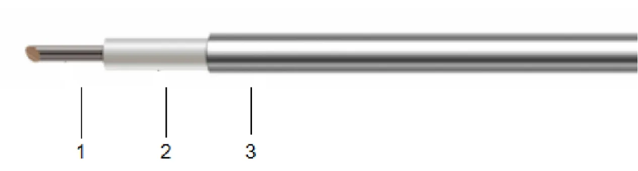
When your RF design cannot tolerate a single dB of uncertainty, flexible cables fall short. The CF Series semi-rigid coaxial cable—with its seamless copper tube outer conductor and solid PTFE dielectric—delivers 165 dB of shielding effectiveness and exceptional amplitude stability from DC to 40 GHz. Every assembly is built to preserve signal integrity in the most space-constrained, thermally demanding environments.
Seamless Copper Tube & 165 dB Shielding
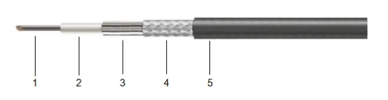
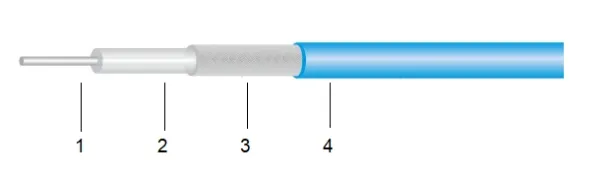
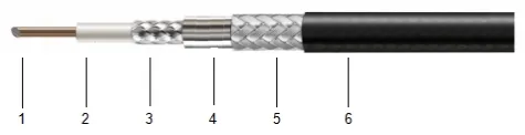
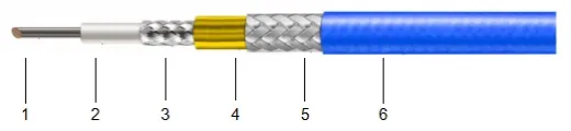
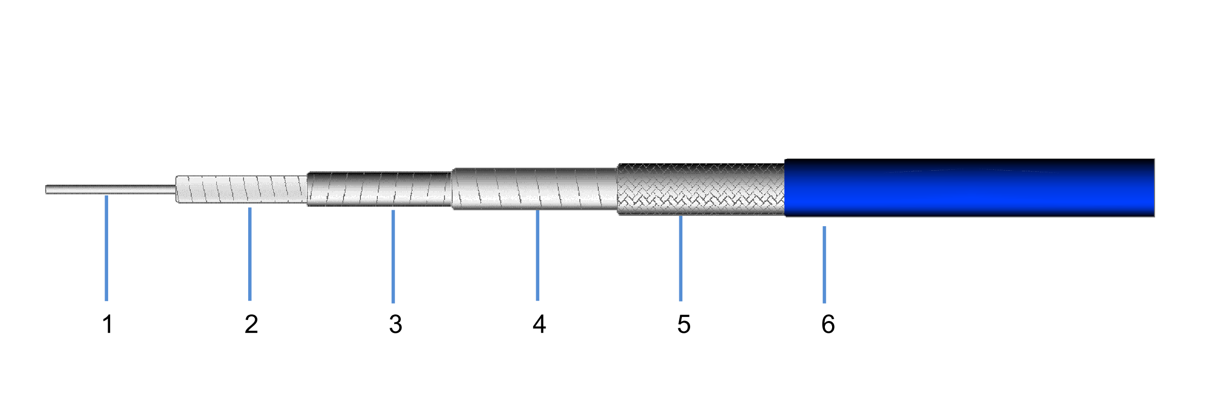
The seamless copper outer conductor with tri-metal plating creates a near-perfect Faraday cage. With 165 dB minimum shielding effectiveness, cross-talk and EMI ingress are effectively eliminated—even in dense multi-channel systems where adjacent cables carry high-power signals.
Solid PTFE Dielectric & 76% Velocity of Propagation
The low-density PTFE dielectric achieves 76% Vp with a dielectric constant of ~1.73, striking the optimal balance between low insertion loss and compact form factor. Signal delay is predictable and repeatable across the full -55°C to +250°C operating range.
Up to 40 GHz with 2.18 mm OD (CF086)
The CF086 variant packs DC–40 GHz performance into a mere 2.18 mm outer diameter—ideal for dense phased-array feed networks, VNA test port cabling, and semiconductor probe station interconnects where every millimeter counts.
Phase Stable < 750 PPM/°C
The all-metal construction and homogeneous PTFE dielectric ensure thermal phase tracking below 750 PPM/°C. In radar calibration loops, satellite transponder chains, or any phase-critical path, the CF Series maintains electrical length with minimal thermal drift.

Define Your Frequency
Up to 18 GHz: CF250 (6.35 mm OD) offers the lowest loss per meter. Up to 26.5 GHz: CF141 (3.58 mm OD) balances performance and size. Up to 40 GHz: CF086 (2.18 mm OD) is the only choice.
Measure Available Space
Semi-rigid cables hold their shape after bending. CF086 requires a minimum 7 mm static bend radius; CF141 needs 15 mm; CF250 needs 32 mm. Ensure your routing envelope accommodates the chosen cable and its pre-formed bends.
Check Attenuation vs. Power
At 18 GHz: CF086 attenuates ~235 dB/100 m (4.8 kW avg power); CF141 ~150 dB/100 m (14.5 kW); CF250 ~92 dB/100 m (52 kW). Match the cable to your link budget and thermal constraints.
Shielding Degradation in Dense Systems
Braided flexible cables leak RF energy at GHz frequencies, causing cross-talk between adjacent channels. The CF Series seamless copper tube delivers 165 dB shielding—orders of magnitude better than any braided alternative.
Phase Drift with Temperature
In phased-array radar and satellite transponders, thermal phase drift misaligns beamforming. The CF Series all-metal + PTFE construction achieves < 750 PPM/°C, keeping arrays coherent across wide temperature swings.
Bend Radius in Tight Enclosures
Many semi-rigid cables demand bend radii exceeding 2x OD. CF086 bends at just 7 mm (3.2x OD), enabling routing inside compact modules, behind backplanes, and through narrow chassis channels without kinking or impedance discontinuity.
Connector Reliability at Temperature Extremes
Soldered semi-rigid connectors eliminate the mechanical joint found in crimp-style flexible assemblies. Rated from -55°C to +250°C, CF Series assemblies survive thermal cycling that would compromise flexible cable connector retention.
VNA Test & Calibration
Phased Array Radar
Satellite Payloads
Semiconductor ATE
Military Avionics
Microwave Point-to-Point
Ready to Specify Your CF Series Assembly?
Send us your frequency requirements, mechanical layout, and connector preferences. We will return a complete technical proposal with S-parameter data, mechanical drawing, and lead time within 24 hours.
Contact sales@aomicrowave.com