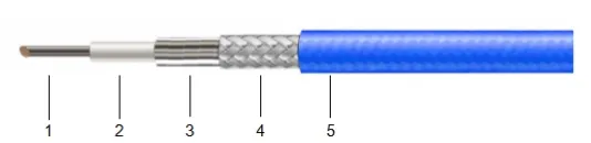
CL Series: Low Loss Coaxial Cable
When avionics and electronic warfare systems demand RF cabling that survives -55C to +165C with 90 dB shielding, the CL Series eliminates guesswork. Nine models (2.33 to 9.40 mm OD) span DC to 40 GHz on one PTFE dielectric and FEP jacket platform. Stranded-conductor variants (CL520S, CL530S) absorb vibration without phase drift, while CL900 and CL940 handle 2.6 kW at 1 GHz for broadband jamming. Qualify the material set once and scale across your entire frequency ladder.
CL Series Low Loss Coaxial Cable
From avionics to electronic countermeasures, the CL Series delivers certified 90 dB shielding and PTFE dielectric stability across nine models spanning DC to 40 GHz. Whether you need the sub-miniature CL230 at 2.33 mm OD for densely packed airframes or the high-power CL940 handling 2.6 kW at 1 GHz for jamming systems, every CL cable combines silver-plated copper conductors with FEP jacketing rated from -55°C to +165°C. Stranded-center-conductor variants (CL520S, CL530S) absorb vibration without compromising phase repeatability — one platform, zero compromises.
Why CL Series?
90 dB Shielding Across All Models
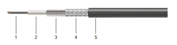
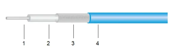
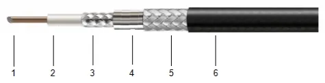
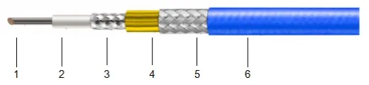
Silver-plated copper foil inner layer + silver-plated copper braid delivers consistent 90 dB shielding from CL230 through CL940. No model downgrades: every cable meets MIL-grade EMI requirements for avionics and electronic warfare environments.
DC to 40 GHz in One Family
CL230 and CL400 reach 40 GHz for mmWave and SATCOM applications; CL500/CL520S/CL530 operate to 26.5 GHz; CL900/CL940 handle broadband high-power at 10 GHz. One connector ecosystem across the entire frequency ladder.
Stranded-Conductor Flex Options
CL520S and CL530S use multi-strand silver-plated copper center conductors that isolate mechanical stress before it reaches solder joints. Ideal for UAVs, vehicle-mounted systems, and any installation subject to continuous vibration or repeated routing changes.
FEP Jacket: -55°C to +165°C
FEP jacketing across all nine models provides a single qualification baseline. No need to track different temperature envelopes per model — from cold-soaked aircraft at altitude to high-temperature engine-bay proximity, the dielectric and jacket hold together.

Which CL Cable Fits Your Project? Start Here.
Instead of scanning every row in the parameter table, answer a few questions below. Each path leads you to the right model.
What is your maximum operating frequency?
Will the cable be bent or moved regularly?
What matters most — space, loss, or power?
Tightest space → CL230 | mmWave 40 GHz → CL230 / CL400 | Flexible → CL520S / CL530S | Balanced → CL500 / CL530 | High power → CL900 / CL940
Add "S" to any model = stranded conductor, for flexible or vibration-prone applications.
Problems CL Series Solves
EMI Failures in Dense Avionics Bays
90 dB shielding effectiveness is standard across every CL model. Silver-plated copper foil + braid construction provides 100% optical foil coverage backed by a conductive braid — your RF lines stay quiet even when routed inches from high-power transmitters and digital processing units.
Cable Fatigue in UAV and Vehicle Systems
Stranded-conductor models (CL520S, CL530S) prevent connector joint fatigue. The multi-strand silver-plated copper core absorbs airframe and road vibration before mechanical stress propagates to solder points — dramatically reducing field RMA rates.
Multi-Vendor Qualification Complexity
Nine models, one dielectric (PTFE), one jacket (FEP), one temperature rating (-55°C to +165°C), one Vp (76%), one shielding level (90 dB). Qualify once, scale across all frequency and power requirements without re-testing environmental envelopes.
Over-Specifying Cable for the Job
The step from CL230 (2.33 mm, 16 g/m) to CL940 (9.40 mm, 208 g/m, 2.6 kW @1 GHz) covers every realistic avionics and EW use case. Pick the smallest model that meets your link budget — no need to carry extra weight or volume for margin you don't need.
Where CL Cables Are Used
Avionics Interconnects
Navigation, comm, and radar RF cabling in fixed-wing and rotary platforms. CL230's 2.33 mm OD and 11 mm bend radius fit tight airframe routing with full 90 dB shielding.
Electronic Countermeasures (ECM)
Broadband jamming pods and self-protection suites. CL900/CL940 handle 2.4–2.6 kW at 1 GHz with low insertion loss across the full jamming band.
UAV & Drone Payloads
Telemetry, video downlink, and C2 RF feeds. CL230 weighs just 16 g/m; CL520S stranded core absorbs airframe vibration without phase drift.
Radar IF & LO Distribution
Phase-matched cable runs for phased-array radar IF and LO signal distribution. 76% Vp across all models ensures consistent electrical length per meter.
SATCOM Ground & Airborne Terminals
L-band, S-band, and Ku-band interconnects. CL400 reaches 40 GHz for Ka-band SATCOM with 265 dB/100m at the top end.
Test & Measurement Instrumentation
VNA, spectrum analyzer, and ATE cabling. CL230/CL400 cover DC–40 GHz in a single bench-friendly form factor with 76% Vp repeatability.
Frequently Asked Questions
Q: What does the "S" suffix mean in CL520S and CL530S?
The "S" indicates a stranded (multi-strand) silver-plated copper center conductor instead of a solid single wire. Stranded construction absorbs mechanical flexing and vibration, making S-models the preferred choice for UAVs, vehicle-mounted systems, and any installation subject to continuous motion. Electrically, stranded and solid models share identical impedance (50 Ω), Vp (76%), shielding (90 dB), and comparable attenuation — the CL530 and CL530S differ by only ~3.4 dB/100m at 10 GHz.
Q: Why do CL530S and CL635 stop at 18 GHz while CL530 reaches 26.5 GHz?
Larger cable diameters shift the cut-off frequency of higher-order propagation modes lower. The CL530S's stranded conductor and CL635's larger dielectric diameter bring the TE₁₁ mode onset below 26.5 GHz. To guarantee clean single-mode TEM operation with stable 50 Ω impedance, we rate these models conservatively to 18 GHz. For 26.5 GHz applications, CL500, CL520S, or CL530 are the correct choices; for 40 GHz, choose CL230 or CL400.
Q: Is 90 dB shielding enough for electronic warfare environments?
Yes. 90 dB shielding effectiveness is the standard across all CL Series models, achieved through silver-plated copper foil (100% optical coverage) plus a silver-plated copper braid. This dual-layer construction is designed specifically for avionics and electronic countermeasures where multiple high-power transmitters and sensitive receivers co-exist in close proximity. For the most extreme co-location scenarios, our CJ Series offers >90 dB shielding.
Q: Do CL cables share the same dielectric and jacket across all models?
Yes. Every CL Series cable uses PTFE dielectric and FEP jacket, with a unified temperature rating of -55°C to +165°C and a consistent 76% Vp. This means you qualify the material set once and apply it across all nine models — no need to re-run outgassing, thermal cycling, or chemical resistance tests when scaling between CL230 and CL940.
Q: How do I estimate loss for my specific cable length?
Scale linearly. Example: a 2-meter CL500 at 6 GHz → 63.20 dB/100m × 0.02 = 1.26 dB. For frequencies between listed points, linear interpolation works well. Need exact S-parameter data for your specific length and frequency combination? Contact our engineering team with your parameters and we'll provide a custom link budget.
Q: Are CL cables RoHS and REACH compliant?
Yes. All CL Series cables use RoHS-compliant materials and meet REACH regulations. Our PTFE dielectric, FEP jacket, and silver-plated copper conductors contain no restricted substances. Compliance documentation is available on request.
Tell Us Your Setup — We'll Recommend the Right CL Cable
Share your operating frequency, cable length, environment (airframe, ground vehicle, test bench), and any flexing or space constraints. Our engineering team will get back to you with a model recommendation — no obligation.
Contact Us: sales@aomicrowave.com