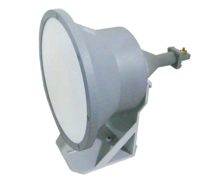
Lens Antenna
Lens Antenna focuses microwave and millimeter-wave signals into highly directional beams with high gain and low sidelobes. Used in radar imaging systems, satellite communication terminals, mmWave communication links, RF research laboratories and advanced antenna systems.
Precision Dielectric Lens Antennas for High-Directivity Millimeter-Wave Beams
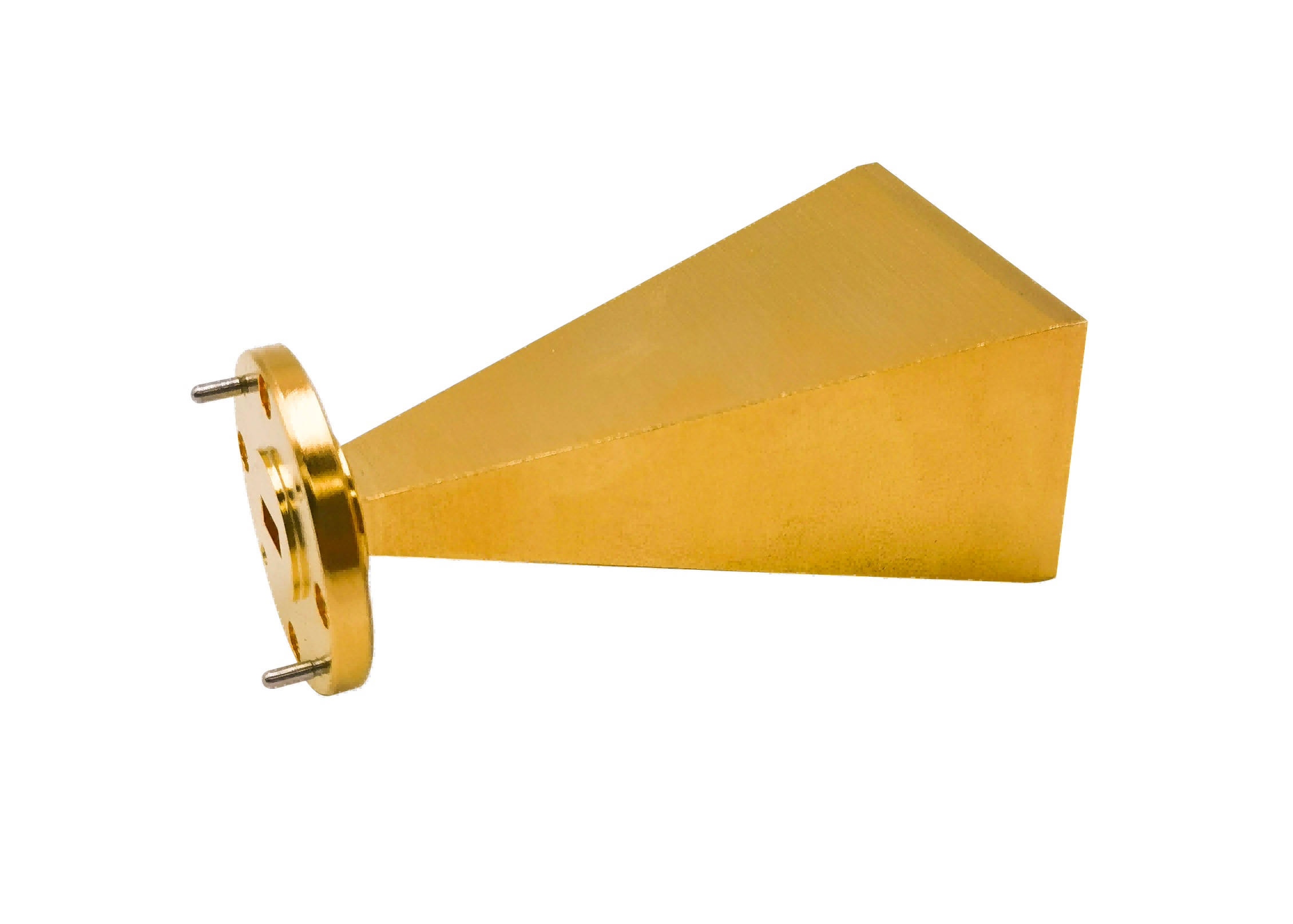
AO Microwave’s high-performance dielectric lens antennas are designed to shape spherical electromagnetic wavefronts into highly directive, narrow plane-wave pencil beams. Consisting of a precision waveguide feed horn and a shaped dielectric lens fabricated from low-loss polymers—such as Rexolite, Teflon (PTFE), and high-density polyethylene—our lens antennas achieve outstanding aperture efficiency up to 110 GHz. Our lens designs deliver exceptionally high gain, a low typical input VSWR of < 1.25:1, and excellent sidelobe suppression across standard millimeter-wave bands (including V-band, E-band, and W-band).
By utilizing the refraction principles of shaped dielectrics, our lens antennas provide a compact alternative to bulky parabolic reflectors. They are critical for 5G/6G point-to-point backhaul, automotive radar test benches (77 to 81 GHz), and high-resolution millimeter-wave imaging systems.
| Part No | Frequency/GHz | VSWR (Max) | Gain/dB (Avg) | E Plane 3dB Beamwidth | H Plane 3dB Beamwidth | E Plane Side-lobe Level/dB (Max) | H Plane Side-lobe Level/dB (Max) | Polarization | Interface Type |
|---|---|---|---|---|---|---|---|---|---|
| AO90-LHA250 | 8.20-12.5 | 2.5 | 25 | 7°~10° | 7°~10° | -15 | -26 | Linear | UBR100 |
| AO75-LHA250 | 9.84-15.0 | 2.5 | 26 | 7°~10° | 7°~10° | -15 | -26 | Linear | UBR120 |
| AO62-LHA150 | 12.4-18.0 | 2.5 | 23 | 7°~10° | 7°~10° | -15 | -26 | Linear | UBR140 |
| AO62-LHA200 | 12.4-18.0 | 2.5 | 26 | 5°~8° | 5°~8° | -15 | -26 | Linear | UBR140 |
| AO62-LHA250 | 12.4-18.0 | 2.5 | 28 | 3°~6° | 3°~6° | -15 | -26 | Linear | UBR140 |
| AO51-LHA100 | 14.5-22.0 | 2.5 | 22 | 9°~12° | 9°~12° | -15 | -26 | Linear | UBR180 |
| AO51-LHA150 | 14.5-22.0 | 2.5 | 25 | 6°~9° | 6°~9° | -15 | -26 | Linear | UBR180 |
| AO51-LHA200 | 18.0-26.5 | 2.5 | 28 | 4°~7° | 4°~7° | -15 | -26 | Linear | UBR180 |
| AO42-LHA80 | 18.0-26.5 | 2.5 | 21 | 9°~12° | 9°~12° | -15 | -26 | Linear | UBR220 |
| AO42-LHA100 | 18.0-26.5 | 2.5 | 23 | 7°~10° | 7°~10° | -15 | -26 | Linear | UBR220 |
| AO42-LHA150 | 18.0-26.5 | 2.5 | 27 | 4°~7° | 4°~7° | -15 | -26 | Linear | UBR220 |
| AO42-LHA200 | 18.0-26.5 | 2.5 | 29 | 3°~6° | 3°~6° | -15 | -26 | Linear | UBR220 |
| AO34-LHA50 | 22.0-33.0 | 2.5 | 19 | 12°~16° | 12°~16° | -15 | -26 | Linear | UBR260 |
| AO34-LHA80 | 22.0-33.0 | 2.5 | 23 | 7°~10° | 7°~10° | -15 | -26 | Linear | UBR260 |
| AO34-LHA100 | 22.0-33.0 | 2.5 | 25 | 6°~9° | 6°~9° | -15 | -26 | Linear | UBR260 |
| AO34-LHA150 | 22.0-33.0 | 2.5 | 29 | 3°~6° | 3°~6° | -15 | -26 | Linear | UBR260 |
| AO34-LHA200 | 22.0-33.0 | 2.5 | 31 | 2°~4° | 2°~4° | -15 | -26 | Linear | UBR260 |
| AO28-LHA50 | 26.5-40.0 | 2.5 | 21 | 10°~13° | 10°~13° | -15 | -26 | Linear | UBR320 |
| AO28-LHA80 | 26.5-40.0 | 2.5 | 25 | 6°~9° | 6°~9° | -15 | -26 | Linear | UBR320 |
| AO28-LHA100 | 26.5-40.0 | 2.5 | 27 | 4°~7° | 4°~7° | -15 | -26 | Linear | UBR320 |
| AO28-LHA150 | 26.5-40.0 | 2.5 | 31 | 3°~5° | 3°~5° | -15 | -26 | Linear | UBR320 |
| AO28-LHA200 | 26.5-40.0 | 2.5 | 33 | 2°~4° | 2°~4° | -15 | -26 | Linear | UBR320 |
The Physics of Wavefront Shaping & Antireflection Grooves
Lens antennas operate on the optical principles of refraction. When a feed horn radiates a spherical wave, the wave components traveling toward the lens center pass through more dielectric material than the outer components. Since waves travel slower in a dielectric medium than in air, the lens introduces a variable delay that flattens the spherical wavefront into a plane wave, producing a highly directive pencil beam.
However, the dielectric boundary between air and the lens can cause reflections, degrading the input VSWR. AO Microwave resolves these reflections by machining concentric antireflection (AR) grooves on both surfaces of the lens. These sub-wavelength grooves act as quarter-wave impedance transformers, reducing return loss and maintaining a low VSWR across the band.
Target Applications & Operational Advantages
By providing highly directive pencil beams with low sidelobes, our lens antennas secure critical millimeter-wave links:
5G/6G mmWave Point-to-Point Backhaul
Function: Radiates highly directive high-capacity backhaul data beams between cellular towers.
Advantage: Ultra-narrow beamwidth and high gain prevent signal spreading, maximizing transmission distance and suppressing interference.
Automotive Radar Testing (77 to 81 GHz)
Function: Radiates collimated signals to simulate target returns on radar test benches.
Advantage: Precision-shaped Rexolite lens delivers a flat, uniform plane wave within a short physical distance, ensuring accurate calibration.
High-Resolution mmWave Imaging
Function: Focuses electromagnetic waves on target surfaces for security scanners or material diagnostics.
Advantage: Low dielectric loss and precise focal alignment enable high spatial resolution and image clarity.
Lens Antenna FAQs
Need high-directivity Dielectric Lens Antennas?
Specify your frequency band, required gain/beamwidth, lens material, and feed interface — we'll quote in 24 hours.