
How Do You Safely Dissipate 20 kW of RF Power? Inside a Custom WR90 Water-Cooled Waveguide Load
See how a custom WR90 water-cooled waveguide load absorbed 20 kW average / 60 kW peak RF power for full-power X-band transmitter testing - and what to check before you buy one.
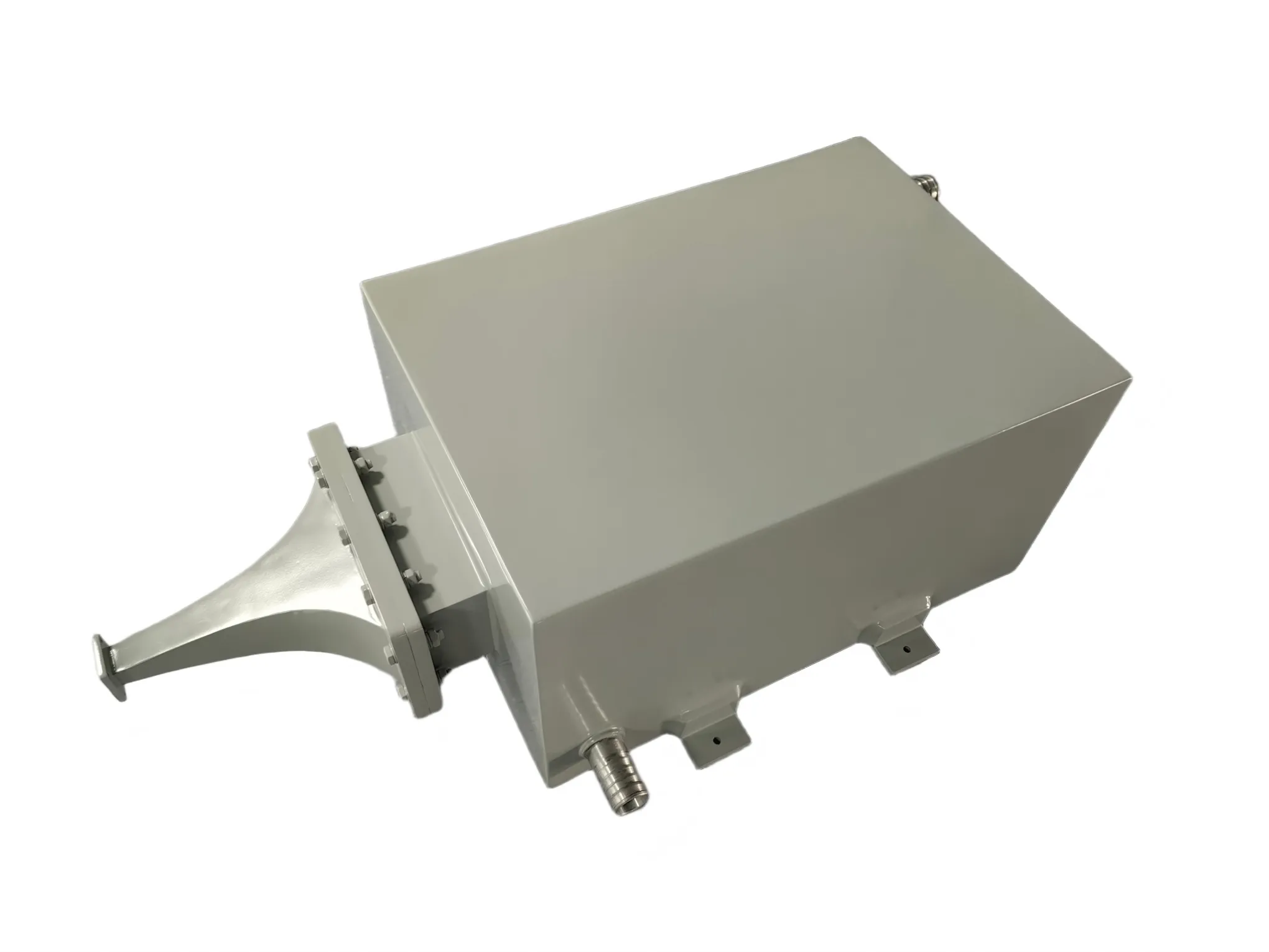
How Do You Safely Dissipate 20 kW of RF Power? Inside a Custom WR90 Water-Cooled Waveguide Load
Picture this: your team has just integrated a high-power X-band transmitter. Before it can ever be connected to an antenna, it has to run at full power on the bench — for hours, not minutes. Every one of those kilowatts has to go somewhere. If that energy reflects back toward the output stage, you can lose a traveling-wave tube or solid-state amplifier worth more than the entire test setup.
That was the problem one customer brought to AO Microwave two months ago. The answer was a custom WR90 water-cooled waveguide dummy load rated for 20 kW average power and 60 kW peak power — and getting there took three design revisions, a compressed production schedule, and a plywood crate built to fit exactly one product. Here is how it worked, and what to know before specifying a load like this yourself.
Why Full-Power Testing Needs a Load — Not an Antenna
High-power transmitters for radar, satellite uplinks, and medical systems can rarely be tested at rated output into open air. Radiating from a lab bench creates interference and regulatory problems, and anechoic facilities are expensive. So engineers terminate the line into a high-power waveguide load — a matched resistor inside a waveguide housing that converts RF energy into heat and dissipates it safely.
At these power levels, the quality of the match is not a detail; it is the whole game. The fraction of reflected power is ((VSWR−1)/(VSWR+1))² — a relationship covered in every microwave engineering text, with Pozar's Microwave Engineering as the classic reference. A VSWR of 1.25 sounds unremarkable until you run the numbers: roughly 1.2% of 20 kW, about 250 watts, traveling back toward a transmitter that may tolerate only a fraction of that. This is why we held the load to a maximum VSWR of 1.25 across the full 8.5–11.0 GHz band, and why we verify it on a network analyzer before anything ships.
Why Water Cooling — and Why WR90
WR90 is the workhorse rectangular waveguide of X-band, covering roughly 8.2–12.4 GHz under the standard EIA waveguide designation system. It is the band of marine radar, air traffic control radar, satellite links, and compact medical linear accelerators — exactly the systems that push tens of kilowatts through a flange.
At 20 kW continuous, no finned aluminum body will survive on convection alone. Water is the pragmatic choice: its specific heat of about 4,180 J/(kg·K) (CRC Handbook of Chemistry and Physics) is among the highest of any common fluid, so a modest flow rate carries away heat that would otherwise damage the absorbing element. This unit routes coolant through a jacket around the load body, with clearly marked water ports — and the cooling system must be running before RF power is applied.
The delivered unit, in brief:
- Frequency range: 8.5–11.0 GHz, WR90 waveguide
- Average power: up to 20 kW (water-cooled)
- Peak power: up to 60 kW at 500 µs pulse width, 30% duty cycle
- VSWR: 1.25 maximum across the band, 50 Ω system
- Flanges: FBP100 (cover) / UBR100
- Construction: aluminum body, chromate conversion inside, anticorrosion grey paint outside, 765 mm long
- Operating temperature: −40°C to +70°C
Three Design Revisions, One Hard Deadline
The specification sheet looks simple. Getting there was not. The first revision traded absorber geometry against cooling-jacket volume; the second refined the transition section to keep VSWR flat at band edges, where reflections are hardest to suppress; the third locked the flange configuration and thermal margins the customer's engineers asked for. Three versions, each reviewed line by line with the customer's team — because a 20 kW load is not a catalog item you gamble on.
Once the design froze, the clock became the enemy. The customer's integration milestone did not move, so neither could we. Production ran on an expedited schedule, final VSWR and power-handling checks were completed on time, and the unit shipped as promised.
Then came the part most suppliers never think about: how it arrives. A 765-millimeter aluminum body does not belong loose in a standard carton. We built a custom plywood crate fitted to the unit's exact dimensions, so nothing shifts in transit and the machined flange faces arrive unmarked. We also included a long wrench, free of charge — tightening FBP100 flange bolts with a short spanner in a cramped equipment room is a small frustration better solved on our side. Small gesture, real difference at installation time.
What This Means for Your Project
Before specifying a high-power dummy load, get answers to four questions:
- Average versus peak power: a load that survives 60 kW pulses may still fail at 20 kW continuous — ask for both ratings and the duty cycle they were measured at.
- VSWR across the whole band: insist on the worst-case figure, not a mid-band typical value.
- Cooling interface: confirm flow rate, port sizes, and interlock provisions before installation day.
- Delivery certainty: custom hardware with a hard integration date needs a supplier who has already rehearsed the expediting path.
Whether you need a one-off water-cooled load or a standard waveguide termination from stock, the principle is the same: the load should be the most boring component in your test chain — the one you never think about again after installation.
Frequently Asked Questions
Q: What is a waveguide dummy load used for?
It terminates a waveguide line in its characteristic impedance, absorbing RF power as heat. Engineers use it to test transmitters at full power without radiating from an antenna, and to provide a matched termination during commissioning and troubleshooting.
Q: Why use a water-cooled load instead of an air-cooled one?
Convectively cooled loads are practical up to a few hundred watts, and forced-air designs reach a few kilowatts. Beyond that, water is the reliable option: its high specific heat (about 4,180 J/(kg·K)) carries away multi-kilowatt heat loads reliably.
Q: What VSWR should a high-power dummy load have?
For transmitter-grade testing, look for 1.25 or better across the full band — and at rated power, not only at low drive levels. Lower VSWR means less reflected power reaching the source; at 20 kW, even small reflections represent hundreds of watts.
Q: Can I apply full RF power before turning on the water cooling?
No. The water cooling system must be functioning properly before RF power is applied. Running even briefly without coolant can permanently damage the absorbing element — build a flow interlock into your setup.
Q: What is the difference between FBP100 and UBR100 flanges?
Both are standard flange types for WR90 (X-band) waveguide: FBP100 is a cover-style flange, while UBR100 is a grooved variant common on European-specified systems. Match the flange to your mating hardware and confirm gasket specifications before ordering.
Q: How long does a custom high-power load take to build?
This project took two months from design to delivery, including three revisions and an expedited production run. The schedule depends mainly on how many iterations your application demands — AO Microwave quotes custom load projects within 24 hours.
Need a High-Power Load for Your Test Bench?
From standard waveguide terminations to custom water-cooled loads above 20 kW, our engineers will review your frequency, power, and flange requirements and quote within 24 hours.
Contact Our Engineering Team