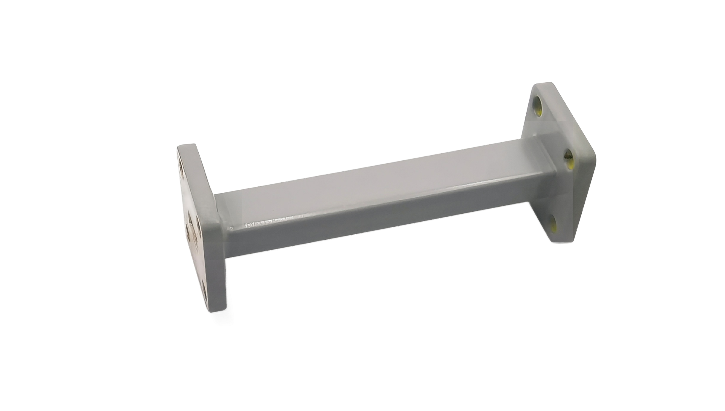
Waveguide Fixed Attenuator
Waveguide Fixed Attenuator provides precise microwave signal attenuation while maintaining stable impedance matching. Suitable for radar transmitters, satellite communication systems, RF test benches and microwave measurement applications.
Precision Waveguide Fixed Attenuators for Calibrated Signal Reduction
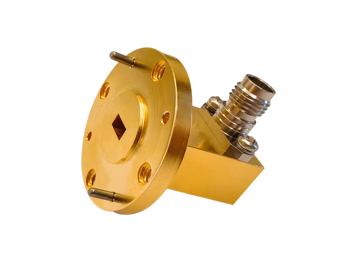
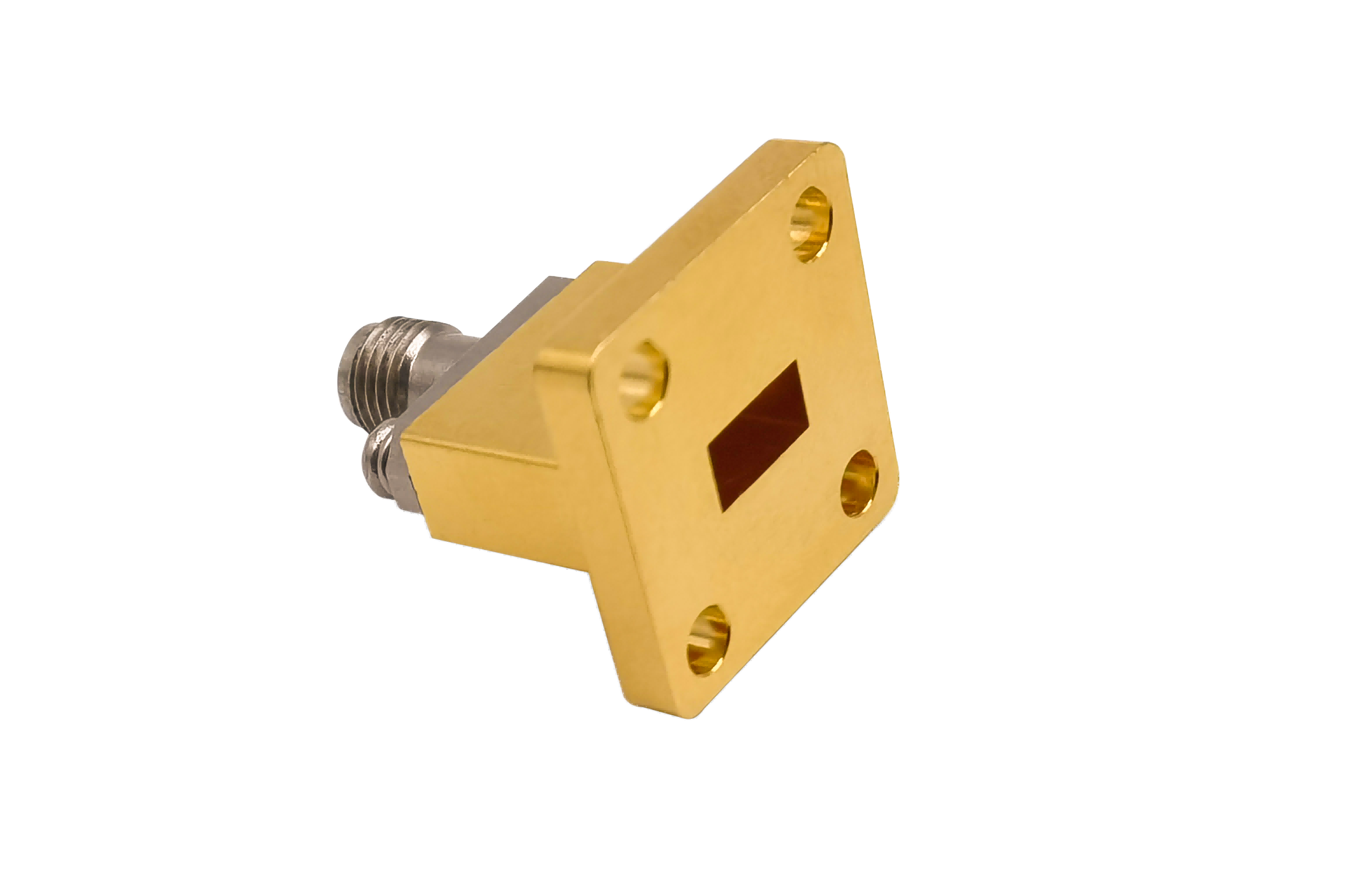
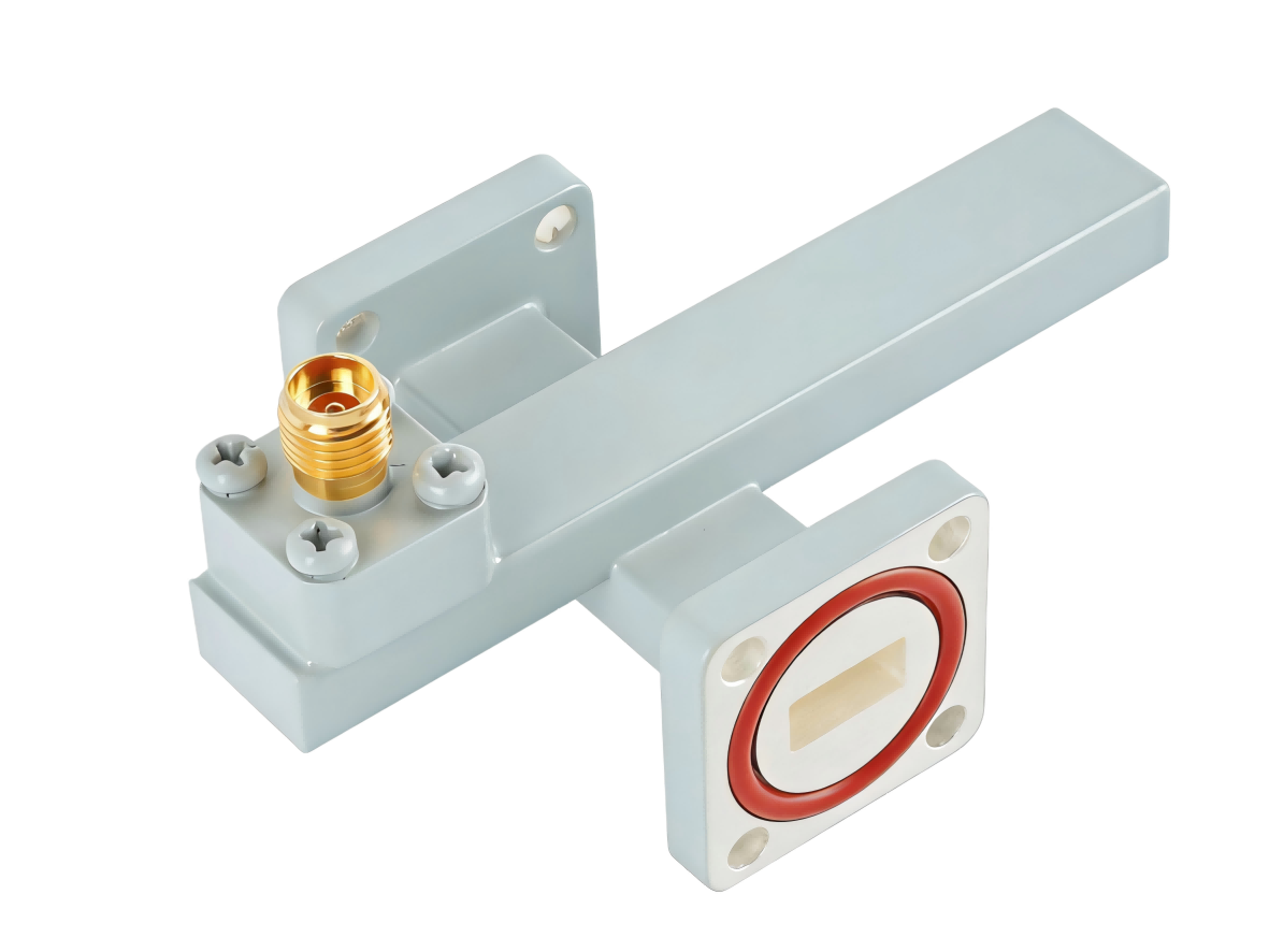
AO Microwave’s waveguide fixed attenuators are designed to reduce electromagnetic power levels by a precise, predetermined value (such as 3, 6, 10, 20, or 30 dB) while preserving system VSWR. Machined from lightweight aluminum and high-conductivity copper alloys, these passive components feature silver-plated internal cavities and gold-plated flange contacts to minimize residual skin-depth loss. Working across standard bands up to 110 GHz (covering WR-90, WR-28, WR-15, and more), our attenuators utilize double-tapered lossy cards to deliver an exceptional typical VSWR of < 1.15:1 and outstanding attenuation flatness (typically ±0.5 dB) across the entire operating band.
By placing highly stable thin-film resistive elements parallel to the maximum E-field at the center of the waveguide, our fixed attenuators provide predictable, bilateral signal absorption. These devices are critical for protecting sensitive receivers, calibrating VNA setups, and balancing signal amplitudes in complex multi-channel transmitter networks.
| Part No | Frequency/GHz | VSWR (Max) | Attenuation/dB | Flange Type |
|---|---|---|---|---|
| AO2300-WFAXPPACG | 0.32-0.49 | 1.25 | 3~30 | UDR3 |
| AO2100-WFAXPPACG | 0.35-0.53 | 1.25 | 3~30 | UDR4 |
| AO1800-WFAXPPACG | 0.41-0.62 | 1.25 | 3~30 | UDR5 |
| AO1500-WFAXPPACG | 0.49-0.75 | 1.25 | 3~30 | UDR6 |
| AO1150-WFAXPPACG | 0.64-0.98 | 1.25 | 3~30 | UDR8 |
| AO975-WFAXPPACG | 0.75-1.15 | 1.25 | 3~30 | UDR9 |
| AO770-WFAXPPACG | 0.96-1.46 | 1.25 | 3~30 | UDR12 |
| AO650-WFAXPPACG | 1.13-1.73 | 1.25 | 3~30 | UDR14 |
| AO510-WFAXPPACG | 1.45-2.20 | 1.25 | 3~30 | UDR18 |
| AO430-WFAXPPACG | 1.72-2.61 | 1.25 | 3~30 | UDR22 |
| AO340-WFAXPPACG | 2.17-3.30 | 1.25 | 3~30 | UDR26 |
| AO284-WFAXPPACG | 2.60-3.95 | 1.25 | 3~30 | UDR32 |
| AO229-WFAXPPACG | 3.22-4.90 | 1.25 | 3~30 | UDR40 |
| AO187-WFAXPPACG | 3.94-5.99 | 1.25 | 3~30 | UDR48 |
| AO159-WFAXPPACG | 4.64-7.05 | 1.25 | 3~30 | UDR58 |
| AO137-WFAXPPCSG | 5.38-8.17 | 1.25 | 3~30 | UDR70 |
| AO112-WFAXPPCSG | 6.57-9.99 | 1.25 | 3~30 | UBR84 |
| AO90-WFAXPPCSG | 8.20-12.5 | 1.25 | 3~30 | UBR100 |
| AO75-WFAXPPCSG | 9.84-15.0 | 1.25 | 3~30 | UBR120 |
| AO62-WFAXPPCSG | 11.9-18.0 | 1.25 | 3~30 | UBR140 |
| AO51-WFAXPPCSG | 14.5-22.0 | 1.25 | 3~30 | UBR180 |
| AO42-WFAXPPCSG | 17.6-26.7 | 1.25 | 3~30 | UBR220 |
| AO34-WFAXPPCSG | 21.7-33.0 | 1.25 | 3~30 | UBR260 |
| AO28-WFAXPPCSG | 26.5-40.0 | 1.25 | 3~30 | UBR320 |
| AO22-WFAXPPCG | 33.0-50.0 | 1.3 | 3~30 | UG-383/U |
| AO19-WFAXPPCG | 40.0-60.0 | 1.3 | 3~30 | UG383/UM |
| AO15-WFAXPPCG | 50.0-75.0 | 1.3 | 3~30 | UG385/U |
| AO12-WFAXPPCG | 60.0-90.0 | 1.35 | 3~30 | UG-387/U |
| AO10-WFAXPPCG | 75.0-110.0 | 1.35 | 3~30 | UG387/UM |
The Physics of Attenuation Flatness & Double-Tapered Designs
Waveguide attenuators reduce power by inserting a resistive sheet, or lossy card, into the path of the electromagnetic wave. In standard TE10 mode propagation, the electric field intensity peaks at the absolute center of the waveguide. To achieve optimal coupling, the resistive card is oriented parallel to this peak E-field. However, if the resistive element is a blunt rectangle, the sudden transition in dielectrics will generate strong reflections, degrading the VSWR.
To resolve this impedance discontinuity, AO Microwave uses a double-tapered lossy card design. By utilizing computer-simulated tapers at both the input and output ends of the card, we ensure the electromagnetic wave transitions smoothly from air dielectric to the lossy substrate. This gradual impedance transition minimizes reflective return loss and stabilizes the attenuation flatness across the entire operating waveguide band, even at millimeter-wave frequencies.
Engineering Challenges at High Attenuation
- Thermal Stress on Thin-Film Resistors: High attenuation levels (e.g., 30 dB) mean the card absorbs 99.9% of the incident RF energy. Without proper thermal conduction, this intense localized heat can cause thin-film resistive coatings to peel or crack.
- Mechanical Concentricity: Even a tiny displacement of 0.03 mm in the card’s alignment can alter its coupling to the E-field, shifting the nominal attenuation value.
- Corrosion Prevention: Hermetic and passivated sealing is critical to protect the internal resistive film from humidity and prevent oxidation-induced attenuation drift.
Waveguide Fixed Attenuator FAQs
Need high-precision Waveguide Fixed Attenuators?
Specify your WR size, required attenuation (dB), average power, and flange style — we'll quote in 24 hours.