Waveguide Loop Coupler
Waveguide Loop Coupler enables efficient RF signal sampling with high directivity and low insertion loss. Commonly used in radar transmitters, microwave communication equipment and RF test systems.
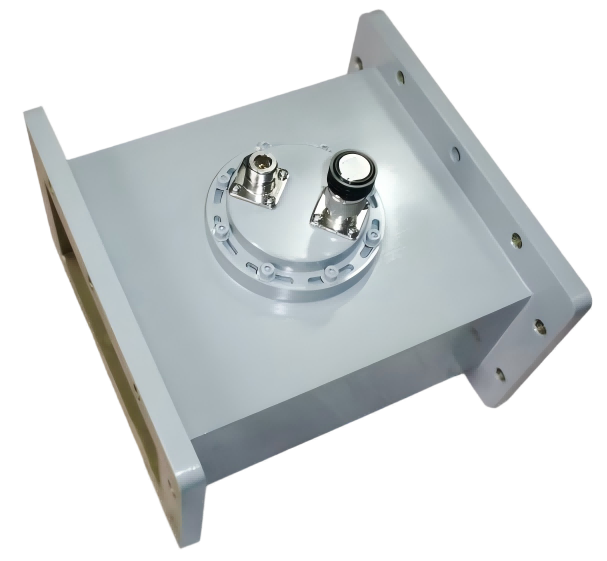
High-Power Waveguide Loop Couplers for Magnetic Field Sampling
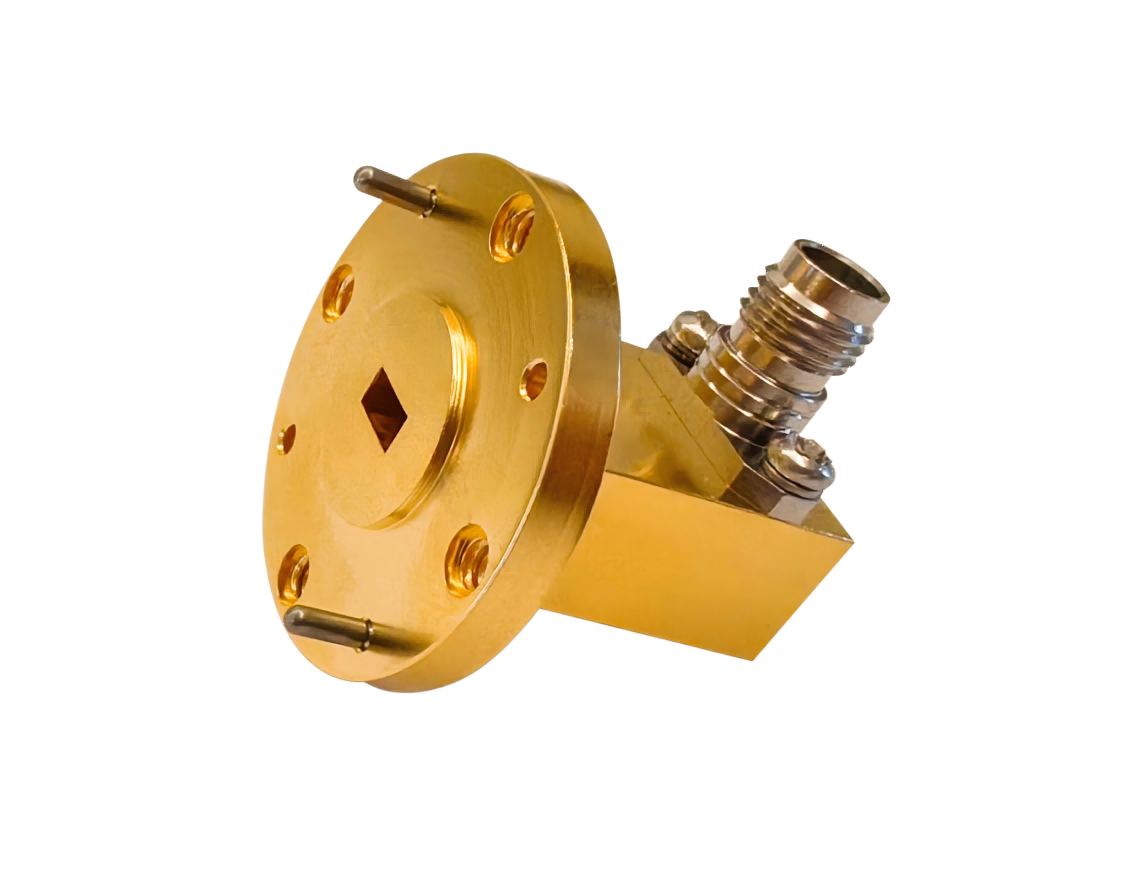
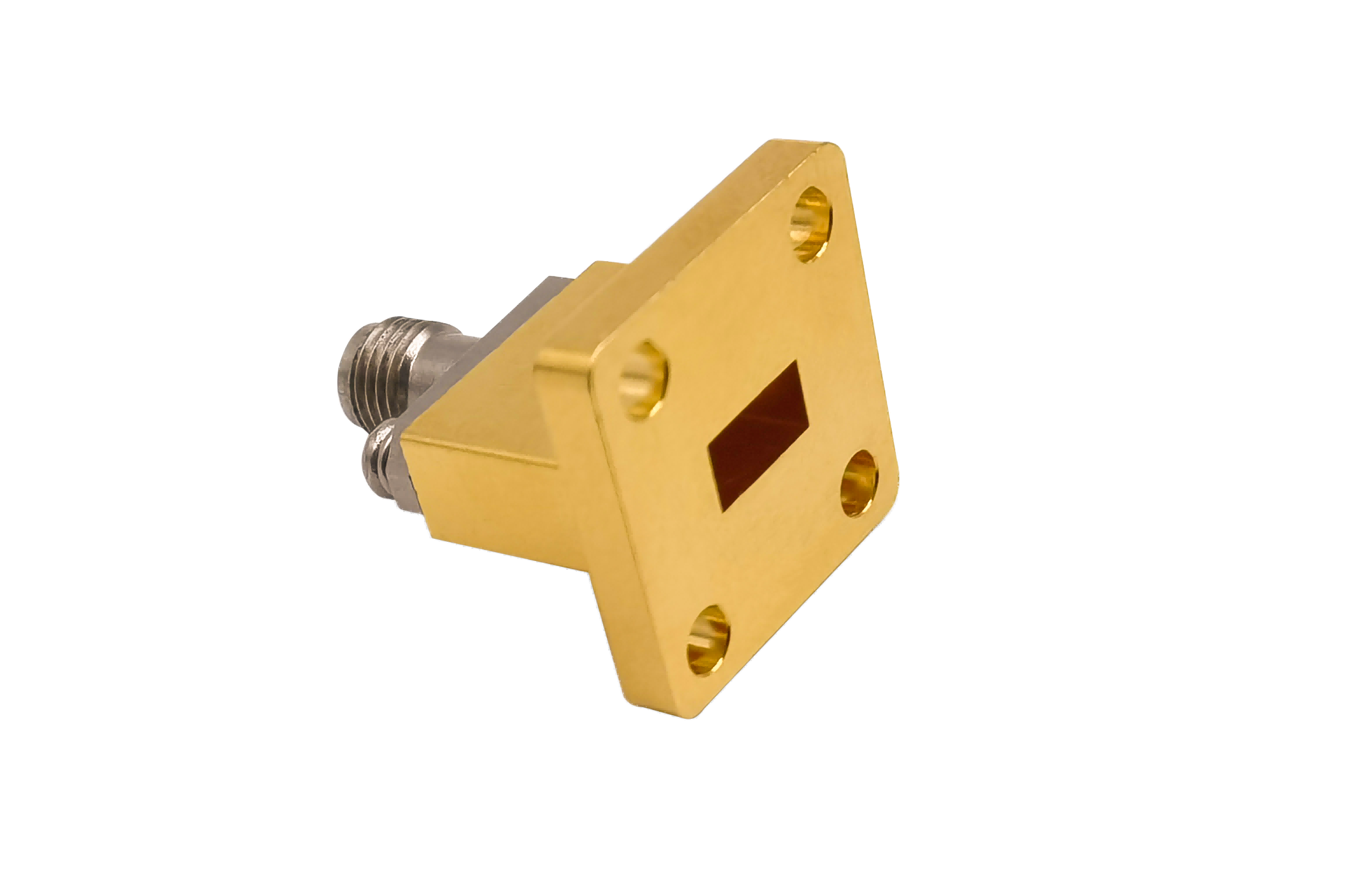
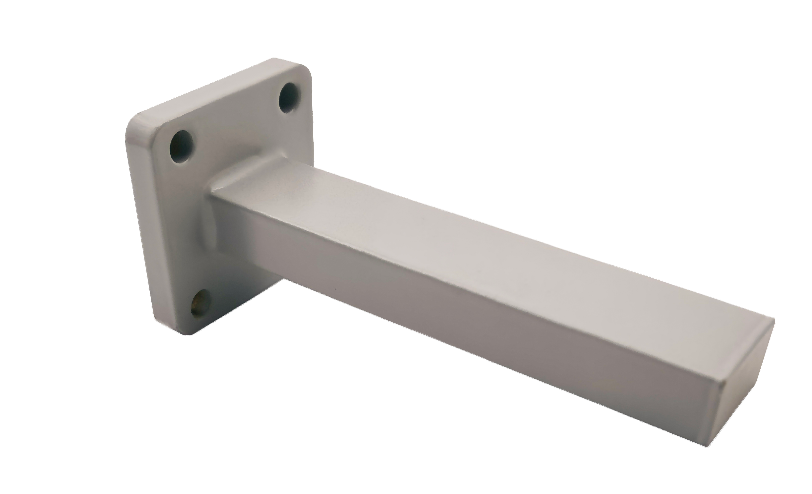
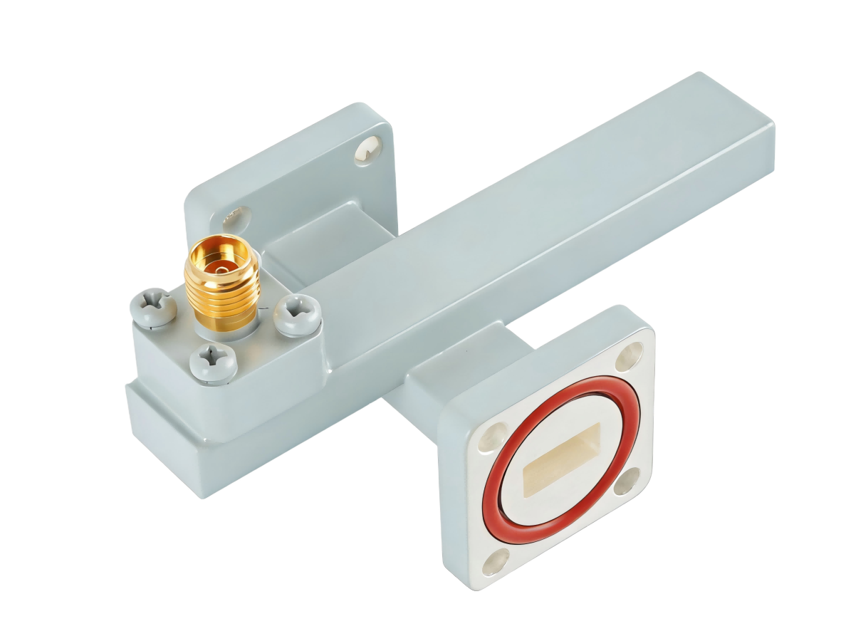
AO Microwave’s waveguide loop couplers provide compact coaxial signal monitoring by tapping the magnetic field (H-field) of rectangular waveguides. Machined from durable brass, copper, and aluminum alloys, these couplers feature a loop element inserted near the narrow waveguide wall where the H-field lines are dense. Operating across standard bands, our loop couplers deliver loose, highly isolated coupling values (typically 30 to 50 dB) and maintain a low mainline VSWR. These devices are ideal for real-time power monitoring in high-power transmitters and industrial microwave heating systems.
To ensure consistent calibration and prevent thermal drift, our loop couplers are equipped with rugged locking mechanisms to secure the loop position. They provide a compact, lightweight monitoring solution that can handle high peak powers without the bulk of multi-hole broadwall couplers.
| Part No | Frequency/GHz | Main VSWR (Max) | Sec VSWR (Max) | IL/dB (Max) | Coupling Optional/dB | Directivity/dB (Min) | Flange Type | Connector Type |
|---|---|---|---|---|---|---|---|---|
| AO975-WHCXNKPPACG | 0.75-1.15 | 1.1 | 1.25 | 0.2 | 20~60 | 15 | UDR9 | N Female |
| AO770-WHCXNKPPACG | 0.96-1.46 | 1.1 | 1.25 | 0.2 | 20~60 | 15 | UDR12 | N Female |
| AO650-WHCXNKPPACG | 1.13-1.73 | 1.1 | 1.25 | 0.2 | 20~60 | 15 | UDR14 | N Female |
| AO510-WHCXNKPPACG | 1.45-2.20 | 1.1 | 1.25 | 0.2 | 20~60 | 15 | UDR18 | N Female |
| AO430-WHCXNKPPACG | 1.72-2.61 | 1.1 | 1.25 | 0.2 | 20~60 | 15 | UDR22 | N Female |
| AO340-WHCXNKPPACG | 2.17-3.30 | 1.1 | 1.25 | 0.2 | 20~60 | 15 | UDR26 | N Female |
| AO284-WHCXNKPPACG | 2.60-3.95 | 1.1 | 1.25 | 0.2 | 20~60 | 15 | UDR32 | N Female |
| AO229-WHCXNKPPACG | 3.22-4.90 | 1.1 | 1.25 | 0.2 | 20~60 | 15 | UDR40 | N Female |
| AO187-WHCXNKPPACG | 3.94-5.99 | 1.1 | 1.25 | 0.2 | 20~60 | 15 | UDR48 | N Female |
| AO159-WHCXNKPPACG | 4.64-7.05 | 1.1 | 1.25 | 0.2 | 20~60 | 15 | UDR58 | N Female |
| AO137-WHCXNKPPCSG | 5.38-8.17 | 1.1 | 1.25 | 0.3 | 20~60 | 15 | UDR70 | N Female |
| AO112-WHCXNKPPCSG | 6.57-9.99 | 1.1 | 1.25 | 0.3 | 20~60 | 15 | UBR84 | N Female |
| AO90-WHCXNKPPCSG | 8.20-12.5 | 1.1 | 1.25 | 0.3 | 20~60 | 15 | UBR100 | N Female |
The Electromagnetics of Magnetic Field (H-Field) Loop Sampling
Loop couplers operate on the principle of magnetic induction. In rectangular waveguides operating in the dominant TE10 mode, magnetic field lines form closed loops parallel to the waveguide broad walls, with peak intensity occurring near the narrow sidewalls. By inserting a small, conductive wire loop through the narrow wall and aligning its plane perpendicular to the H-field lines, a high-frequency current is induced in the loop.
Because loop coupling is magnetic-based, the coupling value naturally increases with frequency at a rate of 6 dB per octave. To compensate for this frequency slope, AO Microwave incorporates specialized internal loading networks. This ensures a stable, flatter coupling response across the target band and provides an easy way to sample signal power without disrupting mainline transmission.
Overcoming High-Power Arcing Risks
- Multipacting & Ionization Prevention: In high-power transmitter runs, the small loop structure can concentrate electric fields at the wire edges, which can lead to multipacting in vacuum or air ionization at high power. We use rounded loop geometries and precise spacing to minimize this field concentration.
- Mechanical Alignment Stability: The coupling value is highly sensitive to the rotation angle of the loop relative to the magnetic field lines. Our loop couplers feature precision-machined keyed housings to prevent rotation and maintain calibration.
- Negligible Mainline VSWR impact: Placing the loop near the waveguide sidewall keeps the capacitive perturbation low, maintaining a low mainline VSWR (< 1.05).
Waveguide Loop Coupler FAQs
Need reliable Waveguide Loop Couplers?
Specify your WR size, required coupling (30/40/50 dB), coaxial connector, and flange style — we'll quote in 24 hours.