Waveguide Power Divider
Waveguide Power Divider splits microwave signals into multiple output paths with balanced amplitude and low insertion loss. Designed for radar systems, satellite communication networks, RF power distribution and microwave test systems used in aerospace, defense and mmWave applications.
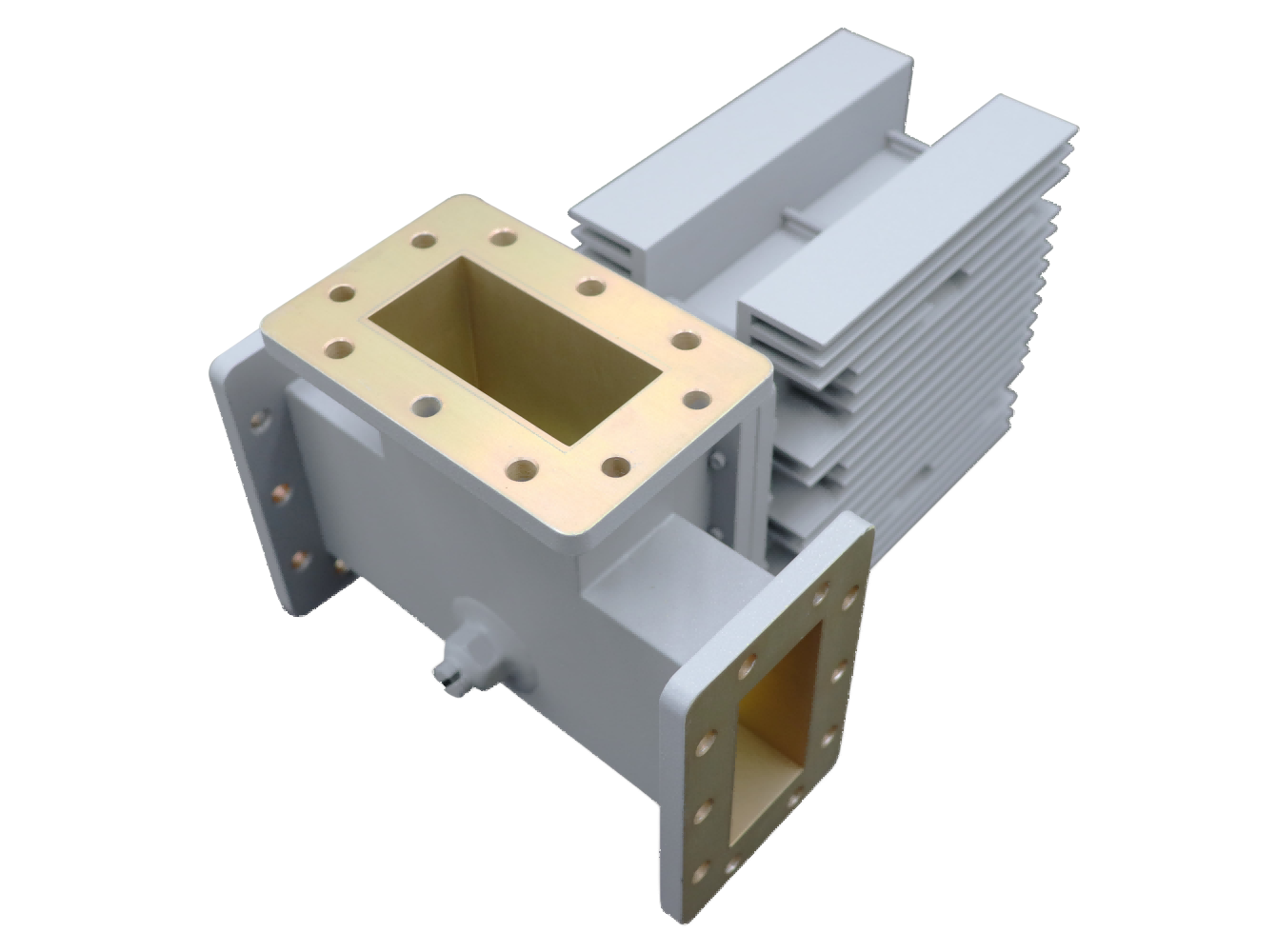
High-Performance Waveguide Power Dividers for Precision Signal Distribution
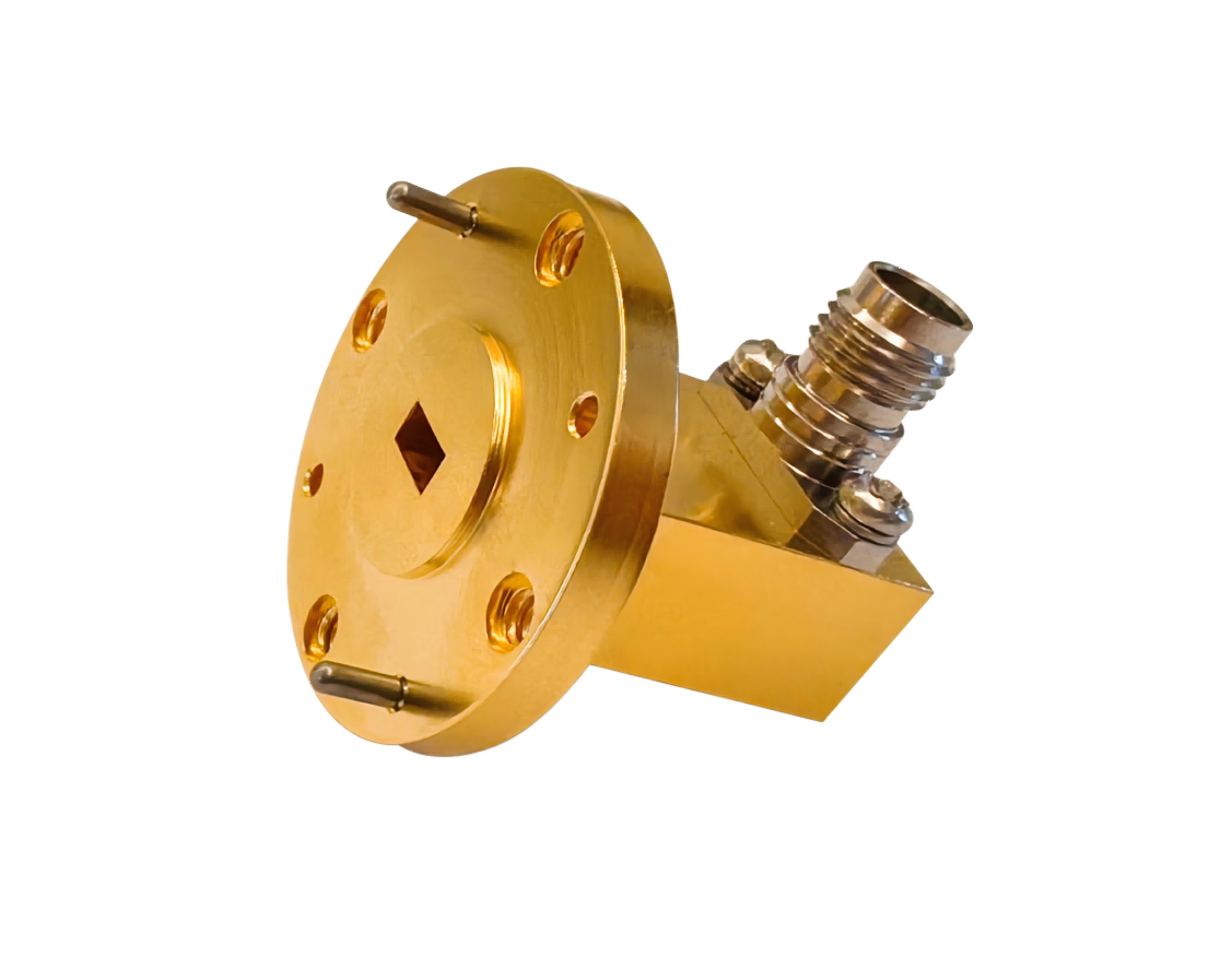
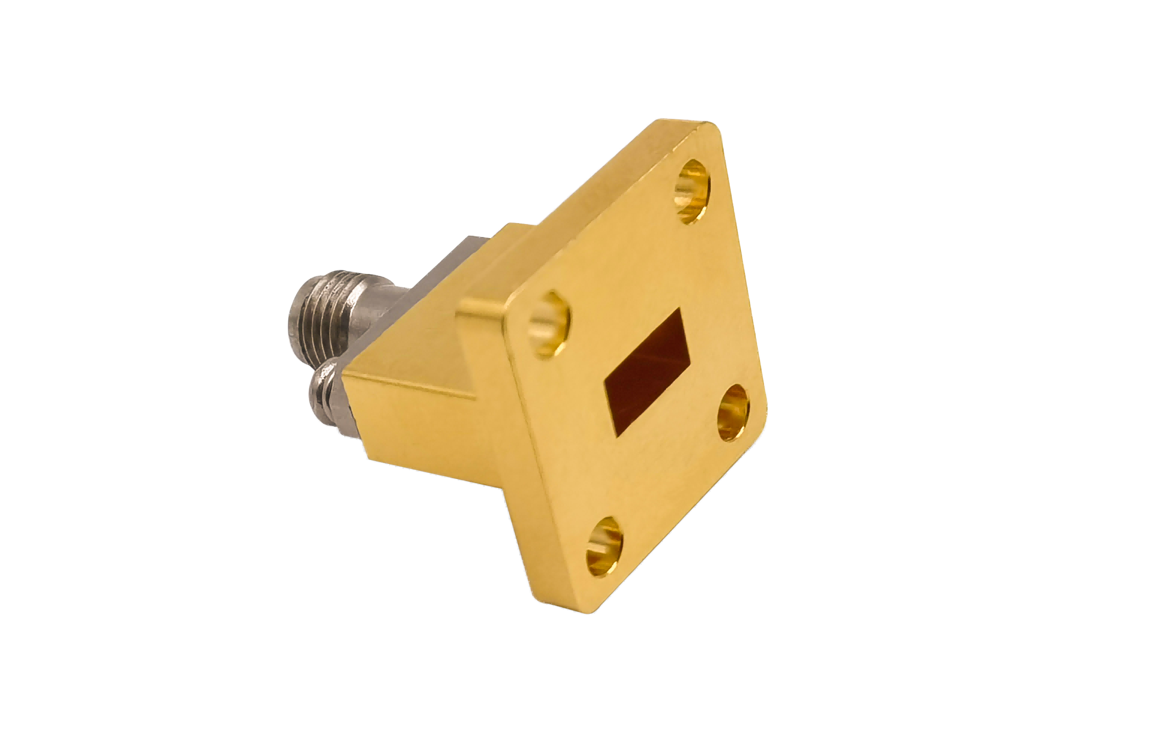
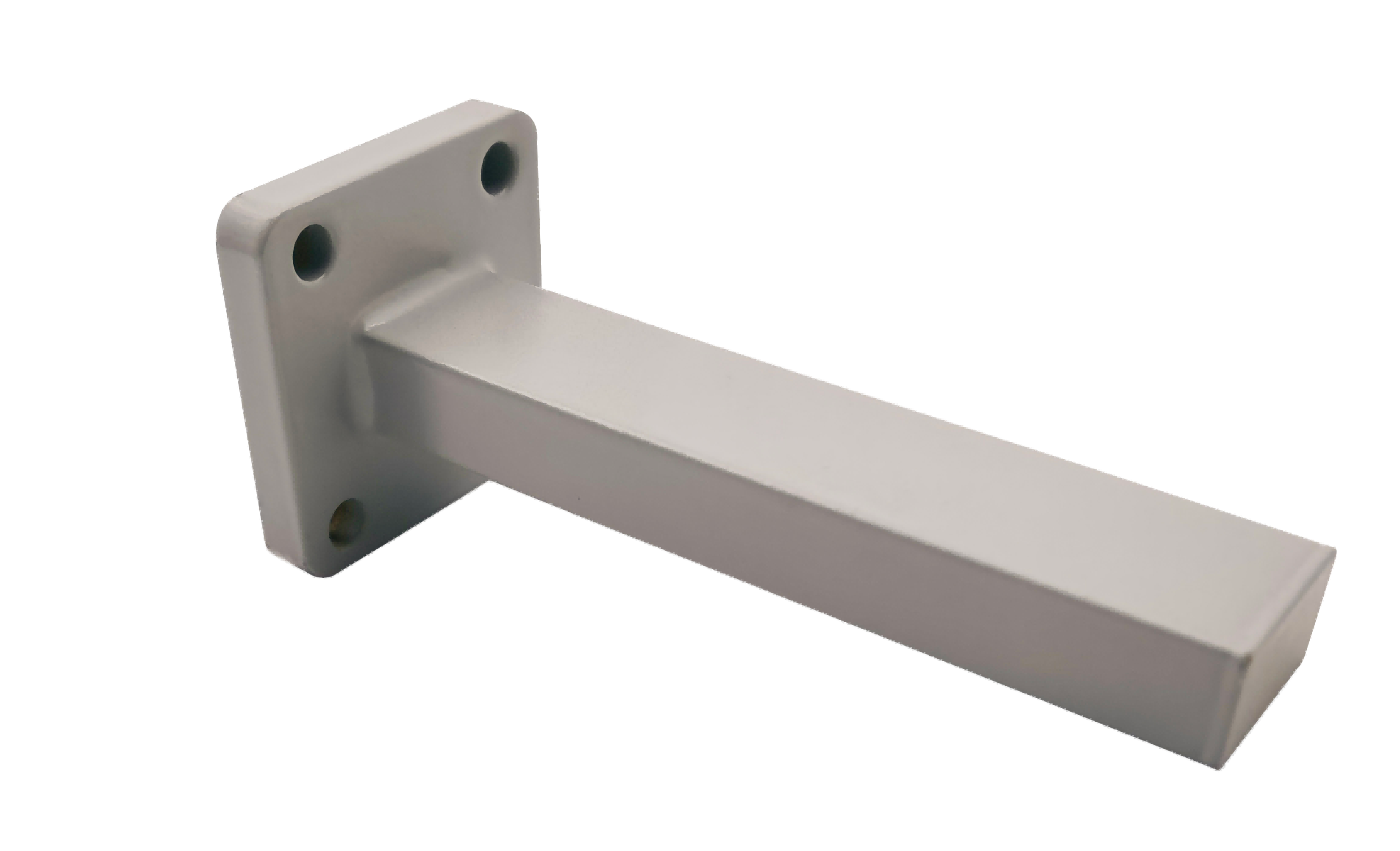
AO Microwave’s waveguide power dividers are designed to split an input signal into multiple output channels with minimum loss. Machined from lightweight aluminum and highly conductive copper blocks, our dividers are available in 2-way, 4-way, and 8-way configurations. Operating up to 110 GHz (WR-90 to WR-10), our multi-port dividers achieve low insertion losses (typically < 0.20 dB), an amplitude balance of < 0.15 dB, and a phase tracking error of < 2.0° across the band.
By utilizing precisely machined bifurcation steps or Wilkinson-style resistive barriers, our power dividers ensure consistent power distribution. They are critical for phased array antenna feed networks, satellite transponder distribution, and multi-channel laboratory test configurations.
| Part No | Frequency/GHz | Bandwidth | VSWR (Max) | IL/dB (Max) | Isolation/dB (Min) | Flange Type |
|---|---|---|---|---|---|---|
| AO2300-WMTPDACG | 0.32-0.49 | 0.2 | 1.2 | 0.2 | 17 | UDR3 |
| AO2100-WMTPDACG | 0.35-0.53 | 0.2 | 1.2 | 0.2 | 17 | UDR4 |
| AO1800-WMTPDACG | 0.41-0.62 | 0.2 | 1.2 | 0.2 | 17 | UDR5 |
| AO1500-WMTPDACG | 0.49-0.75 | 0.2 | 1.2 | 0.2 | 17 | UDR6 |
| AO1150-WMTPDACG | 0.64-0.98 | 0.2 | 1.2 | 0.2 | 17 | UDR8 |
| AO975-WMTPDACG | 0.75-1.15 | 0.2 | 1.2 | 0.2 | 17 | UDR9 |
| AO770-WMTPDACG | 0.96-1.46 | 0.2 | 1.2 | 0.2 | 17 | UDR12 |
| AO650-WMTPDACG | 1.13-1.73 | 0.2 | 1.2 | 0.2 | 17 | UDR14 |
| AO510-WMTPDACG | 1.45-2.20 | 0.2 | 1.2 | 0.2 | 17 | UDR18 |
| AO430-WMTPDACG | 1.72-2.61 | 0.2 | 1.2 | 0.3 | 17 | UDR22 |
| AO340-WMTPDACG | 2.17-3.30 | 0.2 | 1.2 | 0.3 | 17 | UDR26 |
| AO284-WMTPDACG | 2.60-3.95 | 0.2 | 1.2 | 0.3 | 17 | UDR32 |
| AO229-WMTPDACG | 3.22-4.90 | 0.2 | 1.2 | 0.3 | 17 | UDR40 |
| AO187-WMTPDACG | 3.94-5.99 | 0.2 | 1.2 | 0.3 | 17 | UDR48 |
| AO159-WMTPDACG | 4.64-7.05 | 0.2 | 1.2 | 0.3 | 17 | UDR58 |
| AO137-WMTPDCSG | 5.38-8.17 | 0.2 | 1.2 | 0.3 | 17 | UDR70 |
| AO112-WMTPDCSG | 6.57-9.99 | 0.2 | 1.2 | 0.3 | 17 | UBR84 |
| AO90-WMTPDCSG | 8.20-12.5 | 0.2 | 1.2 | 0.3 | 17 | UBR100 |
| AO75-WMTPDCSG | 9.84-15.0 | 0.2 | 1.2 | 0.3 | 17 | UBR120 |
| AO62-WMTPDCSG | 11.9-18.0 | 0.2 | 1.2 | 0.3 | 17 | UBR140 |
| AO51-WMTPDCSG | 14.5-22.0 | 0.2 | 1.2 | 0.3 | 17 | UBR180 |
| AO42-WMTPDCSG | 17.6-26.7 | 0.2 | 1.2 | 0.3 | 15 | UBR220 |
| AO34-WMTPDCSG | 21.7-33.0 | 0.2 | 1.2 | 0.3 | 15 | UBR260 |
| AO28-WMTPDCSG | 26.5-40.0 | 0.2 | 1.2 | 0.3 | 15 | UBR320 |
| AO22-WMTPDCG | 33.0-50.0 | 0.2 | 1.2 | 0.5 | 15 | UG-383/U |
| AO19-WMTPDCG | 40.0-60.0 | 0.2 | 1.2 | 0.5 | 15 | UG383/UM |
| AO15-WMTPDCG | 50.0-75.0 | 0.2 | 1.2 | 0.5 | 15 | UG385/U |
| AO12-WMTPDCG | 60.0-90.0 | 0.2 | 1.2 | 0.8 | 15 | UG-387/U |
| AO10-WMTPDCG | 75.0-110.0 | 0.2 | 1.2 | 0.8 | 15 | UG387/UM |
Impedance Matching in Corporate Multi-Way Dividers
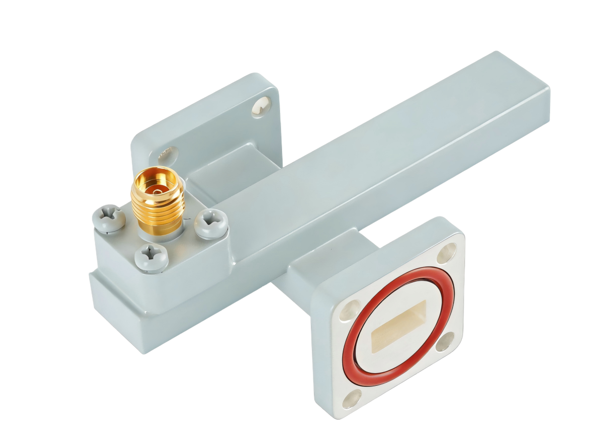
Multi-way corporate power dividers utilize cascading bifurcations to split power. At each split point, the waveguide's characteristic impedance must be managed to prevent reflections, which can degrade the input VSWR.
To resolve these mismatches, AO Microwave incorporates bifurcated step matching networks at each division point. By integrating stepped impedance transformers within the split junction, we transition the impedance from the single input channel to the dual output branches. This precision geometry ensures a low VSWR across all ports and maintains tight amplitude balance across the band.
Target Applications & Operational Advantages
By providing balanced power splitting with low insertion loss, our waveguide power dividers deliver critical performance in active systems:
Phased Array Antenna Feeds
Function: Distributes a single transmitter output equally to multiple radiating antenna elements.
Advantage: Tight amplitude (±0.1 dB) and phase balance (±1.5°) over wide operating bandwidths enable precise beamforming and beam-steering.
Satellite Payload Power Distribution
Function: Splits received transponder signals into multiple receiver channels.
Advantage: Low insertion loss maintains high signal-to-noise ratio, and lightweight aluminum housings help meet aerospace mass budgets.
Multi-Channel Lab Test Arrays
Function: Distributes high-power RF sources to multiple devices under test (DUT) simultaneously.
Advantage: High isolation prevents cross-talk between ports, shielding adjacent DUTs from load-mismatch reflections.
Waveguide Power Divider FAQs
Need high-precision Waveguide Power Dividers?
Specify your WR size, configuration (2-way/4-way/8-way), average power, and flange style — we'll quote in 24 hours.