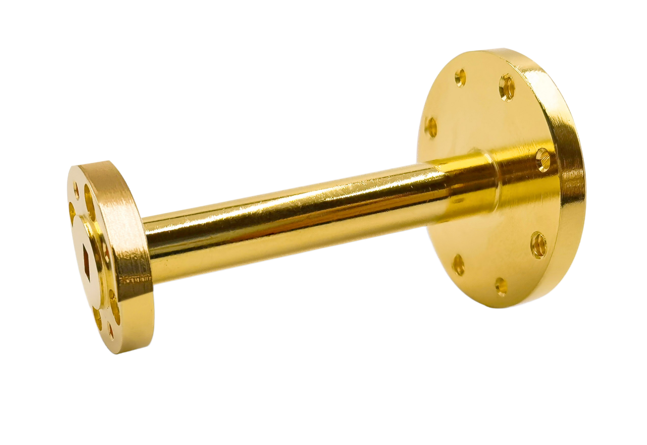
Waveguide Transition
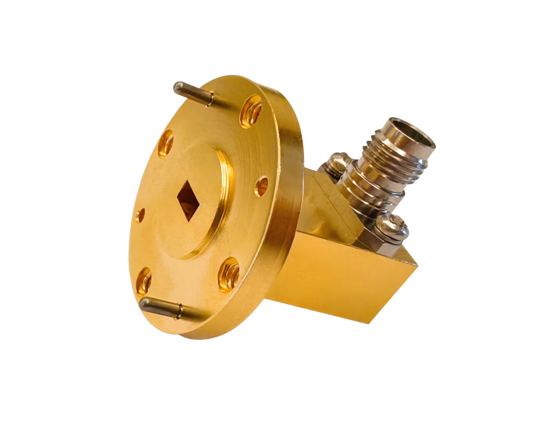
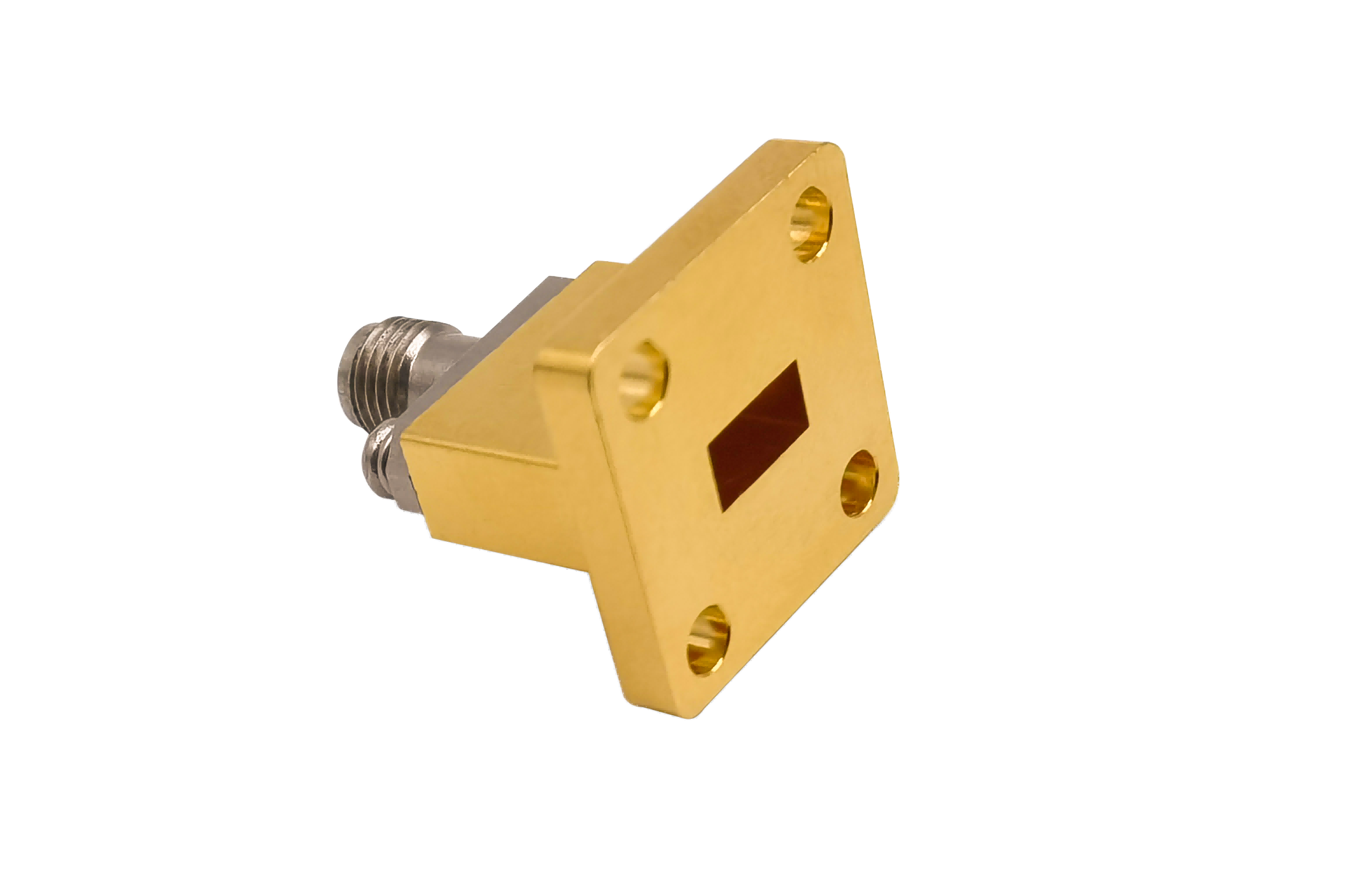
Waveguide Transition components provide efficient signal transfer between different waveguide sizes or types. Designed for microwave communication systems, radar equipment, satellite payloads, aerospace electronics and RF measurement systems.
High-Efficiency Waveguide Transitions for Seamless Band Adapting
AO Microwave's waveguide transitions are designed to connect two components with different physical aperture dimensions or cross-sectional geometries (e.g., rectangular to circular, or overlapping WR-bands) with minimum signal reflection. Working across standard bands up to 110 GHz, our transitions maintain a typical VSWR of < 1.15:1 (with select high-taper designs under 1.08:1) and insertion loss under 0.15 dB. Available in linear taper, exponential, and multi-step Chebyshev profiles, these devices are essential for connecting multi-band equipment.
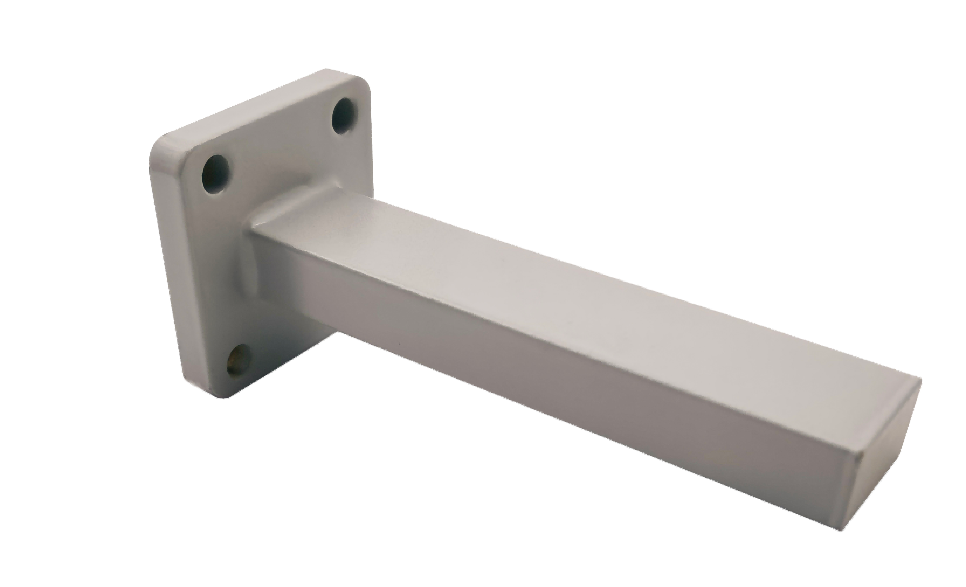
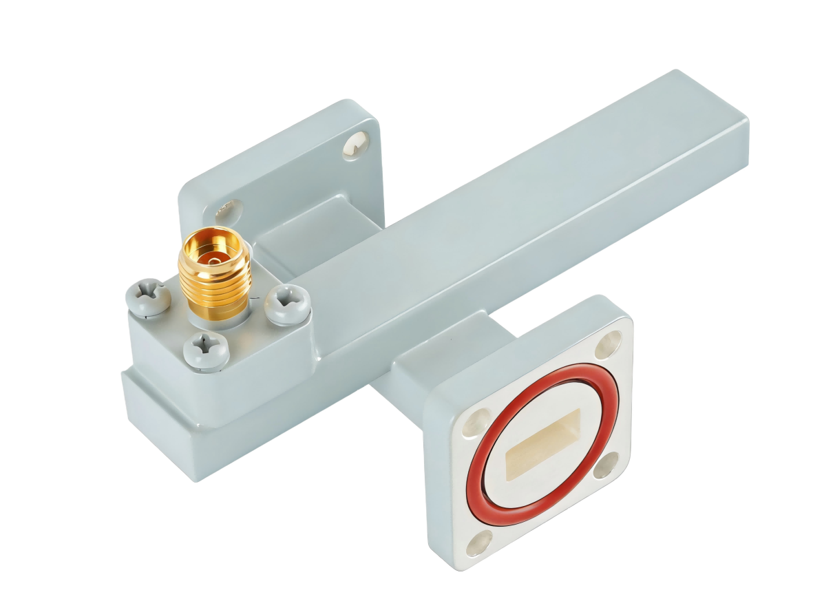
To ensure physical concentricity and consistent transmission behavior, we fabricate our transitions from durable, high-conductivity metals:
- Aluminum: Highly optimized for satellite communication transceivers and payload structures due to its low weight.
- Copper: Preferred in high-power test structures requiring minimum electrical losses.
- Stainless Steel: Designed for cryo-cooled assemblies requiring low thermal conductivity paths.
- Surface Protection: Chemical passivation, high-purity gold or silver plating, and weather-proof external paint to ensure stable long-term performance.
| Part No | Frequency/GHz | VSWR (Max) | IL/dB (Max) | Waveguide Type 1 | Flange Type 1 | Waveguide Type 2 | Flange Type 2 | Standard Length/mm |
|---|---|---|---|---|---|---|---|---|
| AO975770-WAXPPACG | 0.96-1.15 | 1.15 | 0.2 | WR975 | UDR9 | WR770 | UDR12 | X=200 |
| AO770650-WAXPPACG | 1.13-1.46 | 1.15 | 0.2 | WR770 | UDR12 | WR650 | UDR14 | X=200 |
| AO650510-WAXPPACG | 1.45-1.73 | 1.15 | 0.2 | WR650 | UDR14 | WR510 | UDR18 | X=200 |
| AO510430-WAXPPACG | 1.72-2.20 | 1.15 | 0.2 | WR510 | UDR18 | WR430 | UDR22 | X=200 |
| AO430340-WAXPPACG | 2.17-2.61 | 1.15 | 0.2 | WR430 | UDR22 | WR340 | UDR26 | X=200 |
| AO340284-WAXPPACG | 2.60-3.30 | 1.15 | 0.2 | WR340 | UDR26 | WR284 | UDR32 | X=200 |
| AO284229-WAXPPACG | 3.22-3.95 | 1.1 | 0.2 | WR284 | UDR32 | WR229 | UDR40 | X=200 |
| AO229187-WAXPPACG | 3.94-4.90 | 1.1 | 0.2 | WR229 | UDR40 | WR187 | UDR48 | X=200 |
| AO187159-WAXPPACG | 4.64-5.99 | 1.1 | 0.2 | WR187 | UDR48 | WR159 | UDR58 | X=200 |
| AO159137-WAXPPACG | 5.38-7.05 | 1.1 | 0.2 | WR159 | UDR58 | WR137 | UDR70 | X=150 |
| AO137112-WAXPPCSG | 6.57-8.17 | 1.1 | 0.2 | WR137 | UDR70 | WR112 | UBR84 | X=100 |
| AO11290-WAXPPCSG | 8.20-9.99 | 1.1 | 0.2 | WR112 | UBR84 | WR90 | UBR100 | X=60 |
| AO9075-WAXPPCSG | 9.84-12.4 | 1.1 | 0.2 | WR90 | UBR100 | WR75 | UBR120 | X=60 |
| AO7562-WAXPPCSG | 11.9-15.0 | 1.1 | 0.2 | WR75 | UBR120 | WR62 | UBR140 | X=50 |
| AO6251-WAXPPCSG | 14.5-18.0 | 1.1 | 0.2 | WR62 | UBR140 | WR51 | UBR180 | X=50 |
| AO5142-WAXPPCSG | 17.6-22.0 | 1.1 | 0.3 | WR51 | UBR180 | WR42 | UBR220 | X=50 |
| AO4234-WAXPPCSG | 21.7-26.7 | 1.1 | 0.3 | WR42 | UBR220 | WR34 | UBR260 | X=50 |
| AO3428-WAXPPCSG | 26.5-33.0 | 1.1 | 0.3 | WR34 | UBR260 | WR28 | UBR320 | X=50 |
| AO2822-WAXPPCSG | 32.9-40.0 | 1.15 | 0.3 | WR28 | UBR320 | WR22 | UG-383/U | X=50 |
| AO2219-WAXPPCG | 39.2-50.1 | 1.15 | 0.5 | WR22 | UG-383/U | WR19 | UG383/UM | X=50 |
| AO1915-WAXPPCG | 49.8-59.6 | 1.15 | 0.5 | WR19 | UG383/UM | WR15 | UG385/U | X=50 |
| AO1512-WAXPPCG | 60.5-75.8 | 1.15 | 0.5 | WR15 | UG385/U | WR12 | UG-387/U | X=50 |
| AO1210-WAXPPCG | 73.8-91.9 | 1.15 | 0.5 | WR12 | UG-387/U | WR10 | UG387/UM | X=50 |
Waveguide Transition Selection & Engineering Guidelines
Connecting mismatched waveguide segments requires careful planning of the taper profile to ensure stable transmission characteristics:
Linear vs. Non-linear Tapers
Linear Tapers feature a simple constant slope, requiring greater physical length to achieve low VSWR across broad bands. Non-linear Tapers (like Chebyshev or exponential curves) optimize impedance matching over a significantly shorter length, making them ideal for space-constrained installations.
Concentricity & Mechanical Tolerances
Any axial misalignment or shift in center-line concentricity between the input and output waveguides generates unwanted reflection modes. Precision alignment during fabrication is critical, especially when transitioning to millimeter-wave dimensions.
Overcoming Key Waveguide Transition Design Challenges
Preventing High-Order Mode Excitation
Transitioning between different waveguide dimensions too abruptly can excite higher-order wave modes. These parasitic modes alter the transmission path and degrade the overall insertion loss. AO Microwave uses electromagnetic 3D simulation to optimize the taper slope, suppressing high-order modes and keeping insertion loss low across the entire operating band.
Target Applications
- Dual-Band Satellite Terminals: Connects antenna feeds operating across adjacent bands.
- Test Bench Adapting: Adapts VNA ports to devices under test (DUT) with different waveguide sizes.
- Millimeter-Wave (mmWave) Upconverters: Seamlessly routes signals from standard driver output waveguides to smaller high-band modules.
Waveguide Transition FAQs
Need custom Waveguide Transitions?
Tell us your input/output sizes, length constraints, and flange types — we'll quote in 24 hours.