Waveguide Variable Attenuator
Waveguide Variable Attenuator enables adjustable microwave power control for RF systems. Ideal for radar testing, satellite communication equipment, microwave laboratories and RF signal calibration applications.
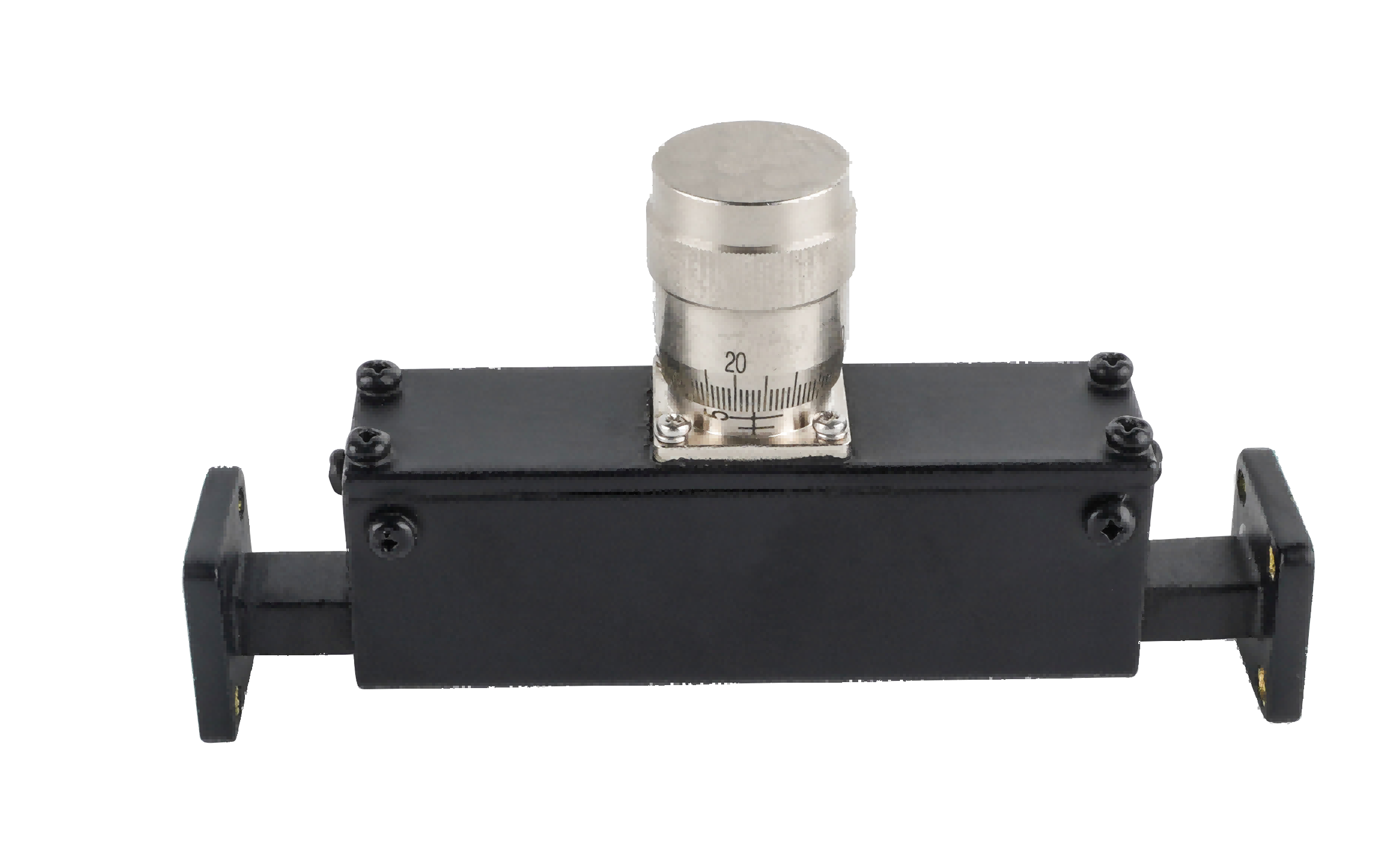
Precision Waveguide Variable Attenuators for Dynamic Level Control
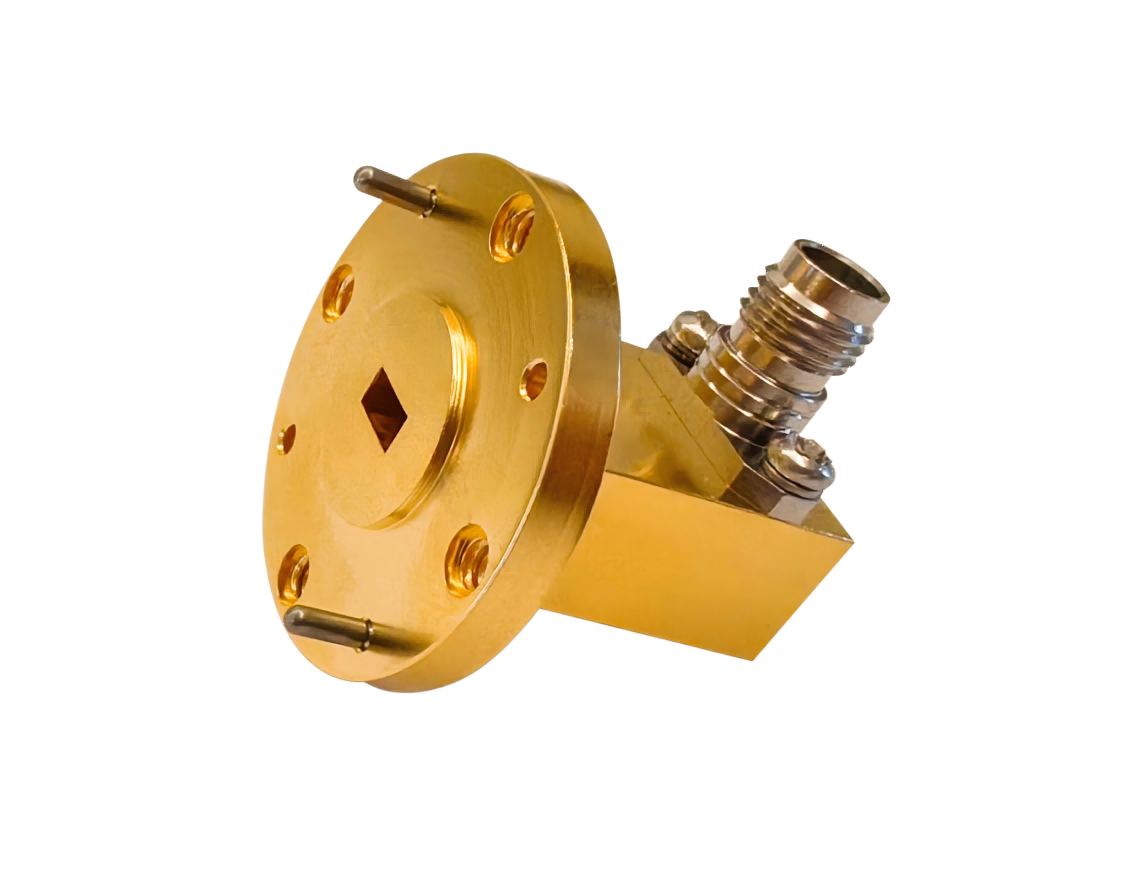
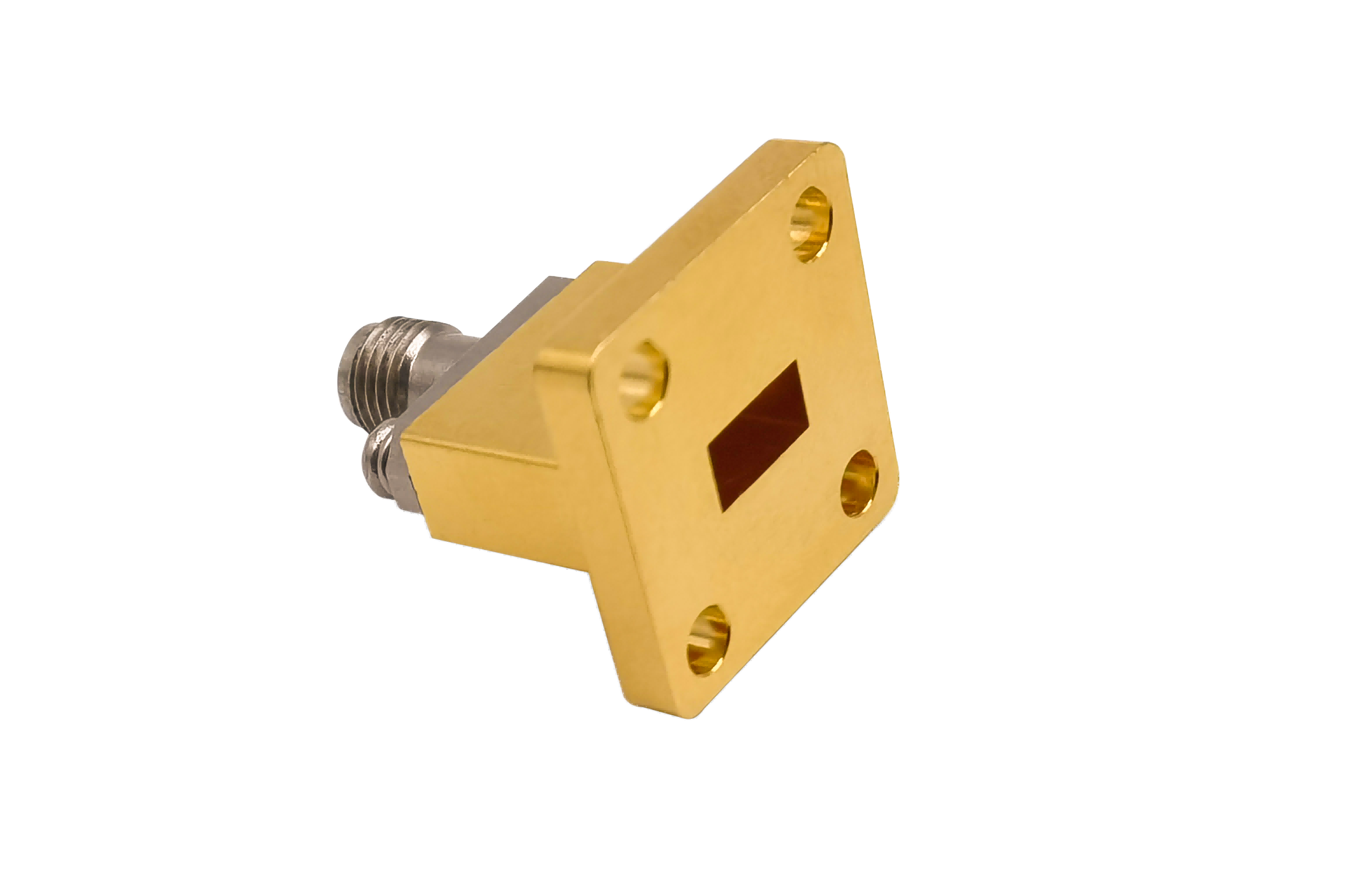
AO Microwave’s waveguide variable attenuators provide continuous, manual adjustment of RF signal levels across a wide dynamic range (typically 0 to 30 dB or 0 to 50 dB) with high mechanical resolution. Precision-machined from aluminum and copper alloys, these mechanical components feature silver-plated internal cavities and smooth-action micrometer dials. Working across standard bands up to 110 GHz, our variable attenuators achieve a typical minimum insertion loss of < 0.5 dB at the zero-setting and a stable VSWR of < 1.25:1 across the entire attenuation range.
By utilizing a highly stable mechanical slot-insertion mechanism to plunge a resistive element into the waveguide cavity, our attenuators allow engineers to precisely tune signal levels in real-time. These variable attenuators are vital for calibrating system sensitivity, balancing gain in multi-beam arrays, and adjusting transceiver paths on microwave test benches.
| Part No | Frequency/GHz | VSWR (Max) | Attenuation Range/dB | Flange Type |
|---|---|---|---|---|
| AO770-WVA30PPACG | 0.96-1.46 | 1.25 | A=0~30 | UDR12 |
| AO650-WVA30PPACG | 1.13-1.73 | 1.25 | A=0~30 | UDR14 |
| AO510-WVA30PPACG | 1.45-2.20 | 1.25 | A=0~30 | UDR18 |
| AO430-WVA30PPACG | 1.72-2.61 | 1.25 | A=0~30 | UDR22 |
| AO340-WVA30PPACG | 2.17-3.30 | 1.25 | A=0~30 | UDR26 |
| AO284-WVA30PPACG | 2.60-3.95 | 1.25 | A=0~30 | UDR32 |
| AO229-WVA30PPACG | 3.22-4.90 | 1.25 | A=0~30 | UDR40 |
| AO187-WVA30PPACG | 3.94-5.99 | 1.25 | A=0~30 | UDR48 |
| AO159-WVA30PPACG | 4.64-7.05 | 1.25 | A=0~30 | UDR58 |
| AO137-WVA30PPCSG | 5.38-8.17 | 1.25 | A=0~30 | UDR70 |
| AO112-WVA30PPCSG | 6.57-9.99 | 1.25 | A=0~30 | UBR84 |
| AO90-WVA30PPCSG | 8.20-12.5 | 1.25 | A=0~30 | UBR100 |
| AO75-WVA30PPCSG | 9.84-15.0 | 1.25 | A=0~30 | UBR120 |
| AO62-WVA30PPCSG | 11.9-18.0 | 1.25 | A=0~30 | UBR140 |
| AO51-WVA30PPCSG | 14.5-22.0 | 1.25 | A=0~30 | UBR180 |
| AO42-WVA30PPCSG | 17.6-26.7 | 1.3 | A=0~30 | UBR220 |
| AO34-WVA30PPCSG | 21.7-33.0 | 1.3 | A=0~30 | UBR260 |
| AO28-WVA30PPCSG | 26.5-40.0 | 1.3 | A=0~30 | UBR320 |
| AO22-WVA30PPCG | 33.0-50.0 | 1.3 | A=0~30 | UG-383/U |
| AO19-WVA30PPCG | 40.0-60.0 | 1.3 | A=0~30 | UG383/UM |
| AO15-WVA30PPCG | 50.0-75.0 | 1.3 | A=0~30 | UG385/U |
| AO12-WVA30PPCG | 60.0-90.0 | 1.3 | A=0~30 | UG-387/U |
| AO10-WVA30PPCG | 75.0-110.0 | 1.3 | A=0~30 | UG387/UM |
Overcoming Backlash & RF Leakage in Mechanical Attenuators
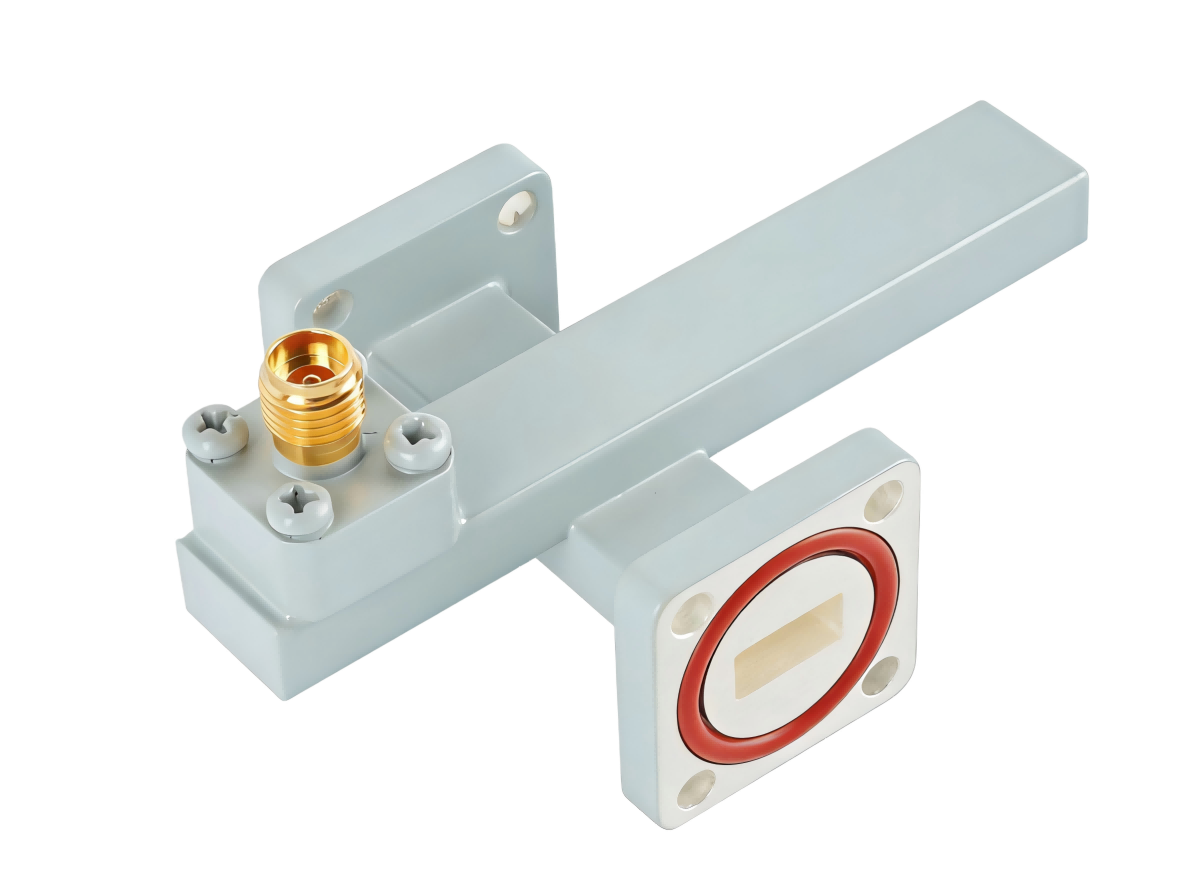
Mechanical variable attenuators utilize a mechanical drive to insert a resistive sheet into the waveguide through a slot in the waveguide wall. When dialing the micrometer, a common engineering challenge is mechanical backlash. Because gear assemblies have small tolerances, turning the dial clockwise to 10 dB may yield a slightly different attenuation value than turning it counter-clockwise to 10 dB.
Additionally, the open slot required to insert the card creates a potential path for RF leakage. At millimeter-wave frequencies, electromagnetic energy can easily leak through this slot, generating EMI interference and degrading measurement accuracy. AO Microwave solves these design challenges by integrating backlash-free drive gearing and surrounding the slot with specialized RF choke structures. This ensures repeatable, bi-directional settings and prevents signal leakage, maintaining stable performance in high-frequency setups.
Key Features & Applications
- High Dial Repeatability: Precision micrometer gear assemblies ensure that setting the dial back to a calibrated index reproduces the exact attenuation level within ±0.1 dB.
- Minimal 0dB Insertion Loss: Retracting the resistive card fully out of the waveguide cavity minimizes residual losses, maintaining insertion losses below 0.5 dB.
- Multi-Band Lab Testing: Ideal for adjustably reducing power levels on VNA receiver test benches and verifying active system dynamic range.
Waveguide Variable Attenuator FAQs
Need high-resolution Waveguide Variable Attenuators?
Specify your WR size, attenuation range (0-30/0-50 dB), average power, and flange style — we'll quote in 24 hours.