
How Do You Handle 100 W at 40 GHz? Meet the WR28 High-Power Waveguide Load That Stays at 1.20 VSWR
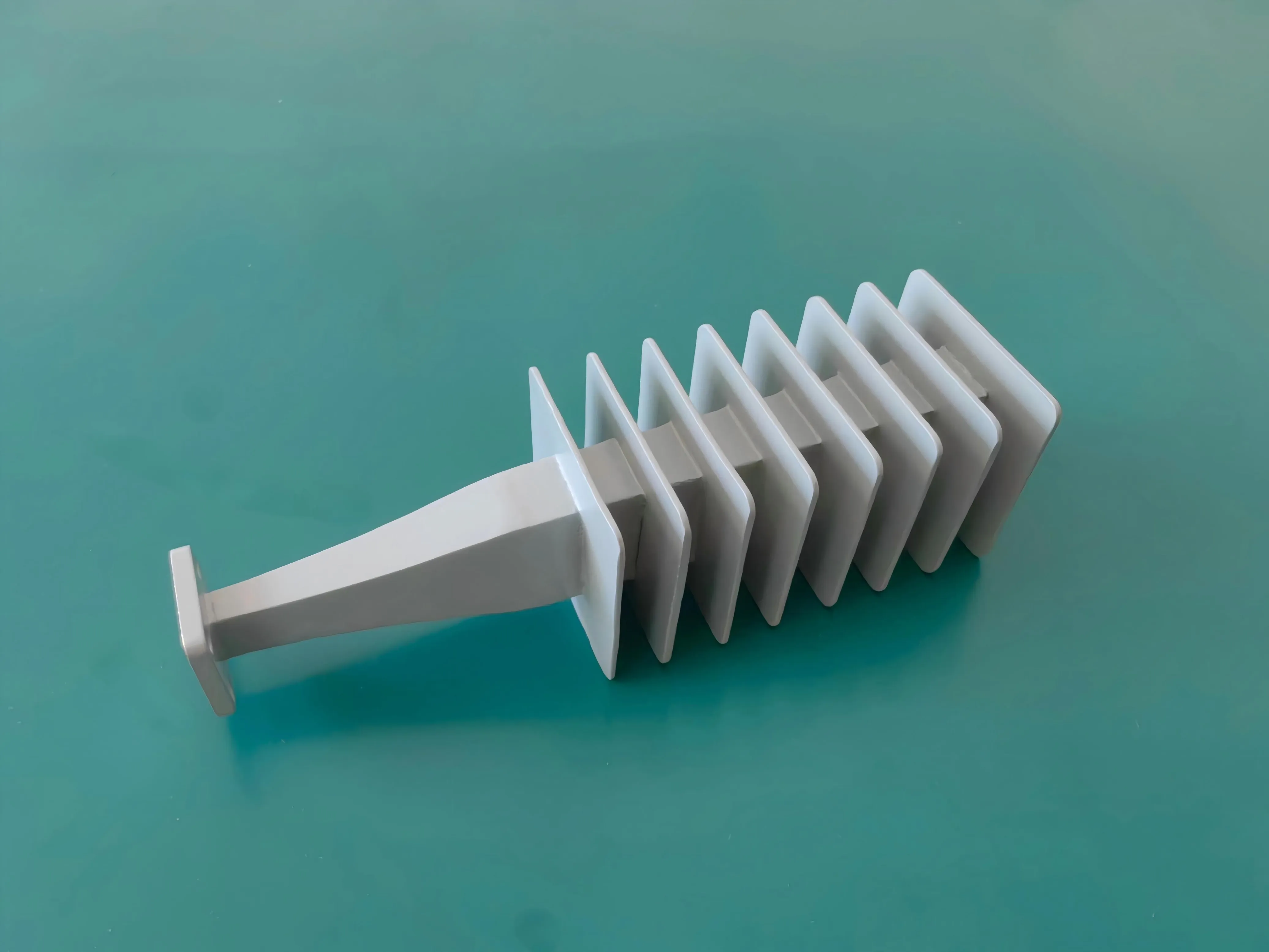
WR28 high-power waveguide load by AO Microwave: 100 W average, 26.5-40 GHz, VSWR 1.20 max (20.8 dB return loss), 135 mm body for Ka-band amp and satcom test. Datasheet in 24 h.
How Do You Handle 100 W at 40 GHz? Meet the WR28 High-Power Waveguide Load That Stays at 1.20 VSWR
Every test bench with a serious Ka-band amplifier has the same quiet problem: where does the forward power go when you need a clean, matched load? Small lab terminations die fast under tens of watts. Coaxial loads become impractical past 26 GHz. And an open or poorly matched port sends reflected power back into your device under test, which turns a straightforward measurement into a mystery.
AO Microwave has just added a WR28 high-power waveguide load to close that gap. It covers the full 26.5-40 GHz band, absorbs 100 W average power, holds VSWR at or below 1.20:1 across the band, and fits in a 135 mm body designed to move heat instead of storing it. If you burn in power amplifiers, soak-test transmitters, or verify satcom uplink subsystems, this is the part of the bench that should be boring. That is exactly the point of a good load.
Why a Ka-band bench needs a load that outrates the device on it
A load is only interesting when it stops working. Until then it quietly absorbs energy, converts it to heat, and lets you trust that nothing is bouncing back into your chain. That trust is harder to earn at millimeter-wave power levels than it looks, because the load is part of the signal path. Its match affects your measurements, and its thermal limit decides how long you can run a test.
Typical WR28 loads in the catalog are rated for fractions of a watt to a few watts, which is fine behind a signal generator and useless behind a power amplifier. The people who order 100 W versions are usually doing one of these:
- Amplifier burn-in and soak testing, where the DUT sits at or near rated output power for hours and the load has to survive the whole shift.
- Transmitter testing into a known impedance when you do not want to radiate; the load works as a dummy load in this role, standing in for the antenna or horn.
- Terminating spare ports on circulators, isolators, and switches in a full-power rack so unused paths never run open.
- Power verification and calibration chains where a 50-ohm coaxial reference is not an option at these frequencies.
In every one of those cases, the cost of a load that is undersized is not the load itself. It is the ruined test day, the skewed data, and the amplifier that sees an unexpected reflection at the worst moment.
WR28 is a busy band right now
WR-28 is the rectangular waveguide size with a recommended operating range of 26.5-40 GHz, which puts it squarely in the Ka band defined by IEEE Std 521. Practical traffic in that window is heavy and getting heavier: the 5G FR2 bands n257 (26.5-29.5 GHz) and n260 (37-40 GHz) set out in 3GPP TS 38.104, Ka-band satellite uplinks around 27.5-31 GHz used by gateways and VSAT terminals, plus defense EW, radar, and EMC test ranges.
The ground segment behind that traffic is expanding quickly. In its Satellite Ground Station Market - Global Forecast to 2030 report, MarketsandMarkets projects the market to grow from USD 40.99 billion in 2025 to USD 82.72 billion in 2030, a 15.1% compound annual growth rate, with the Ku/Ka frequency segment the fastest-growing at 15.4%. More Ka-band transmitters in production and in the field means more benches that need high-power loads, and more engineers who discover that the small termination in the drawer was never meant for this job.
If you are checking whether a WR28 port will fit your existing system, our waveguide size chart lists frequency ranges, inner dimensions, and flange designations from WR-2300 to WR-10 in one table.
WR28 high-power waveguide load and termination, at a glance
| Parameter | Value |
| Waveguide size | WR-28 (R320 / BJ320) |
| Frequency range | 26.5 - 40 GHz (full band) |
| Average power | 100 W (CW) |
| VSWR | ≤ 1.20:1 (return loss ≥ 20.8 dB) |
| Overall length | 135 mm |
| Interface | WR-28 rectangular port, standard UG-599/U square cover flange; other flange styles can be confirmed against your system drawing |
It joins the waveguide loads and terminations family, which already covers standard and low-power units from WR-2300 to WR-10. Full mechanical drawings and a datasheet are available on request, and standard parts carry no minimum order quantity.
What the 1.20 VSWR spec actually buys you
VSWR 1.20:1 corresponds to a return loss of roughly 20.8 dB. Feed 100 W in and about 0.8 W comes back; the other 99.2% is absorbed where it should be. For comparison, several catalog 100 W WR28 waveguide terminations from major distributors spec 1.25:1 maximum, which is about 19.1 dB return loss and just over 1% reflected. The gap looks small on paper, but the spec that matters is the one the load holds across the entire band, not at a spot frequency where the match happens to be best.
At high drive levels the reflected power is not a rounding error. It combines with the forward wave to form standing waves between the load and the source, which can push an already hot amplifier closer to instability and makes forward and reflected power readings drift test to test. A tighter, flatter match keeps burn-in results repeatable and gives you one less variable when you are trying to characterize the device, not the bench.
The 135 mm body is mostly about heat
A waveguide load works by letting the incoming wave run into an absorbing structure that converts RF energy into heat. That is simple enough at low power. It stops being simple at 100 W average through a WR-28 aperture of only 7.112 x 3.556 mm, where the energy is concentrated in a very small cross-section and the temperature of the absorbing element climbs quickly.
The length is the first clue to how the thermal problem was solved. A 1 W lab termination can be a few centimeters long because it barely warms up. A 100 W unit needs room for the absorber to spread the heat along the guide and for the body to conduct it out to the flange, the mounting surface, or the surrounding air. That is why this 100 W waveguide termination runs 135 mm and why its power rating is an average, continuous-wave figure rather than a pulse number.
Two practical notes. First, if you plan to mount the load in a confined enclosure or at altitude, tell us; we will give you a realistic derating recommendation for your airflow and ambient temperature instead of a number copied from a datasheet. Second, if your test involves pulsed signals, send us the pulse width and duty cycle and we will confirm whether the average-power rating covers your waveform.
Waveguide load FAQ
Q: What is a waveguide load, and why is it also called a termination?
A waveguide load is a one-port component placed at the end of a transmission path to absorb RF energy and convert it to heat, so nothing reflects back toward the source. "Load" and "termination" are used interchangeably. It is the waveguide equivalent of a 50-ohm coaxial terminator, and it exists for the same reason: every signal has to stop somewhere, and it should stop cleanly.
Q: Waveguide load vs. attenuator, is there a difference?
Yes. An attenuator reduces power but still lets a controlled portion pass through to the next stage. A load absorbs essentially all of the incident power. If you need to sample or split power for a following circuit, use a coupler or attenuator. If you need to absorb power at the end of a chain, use a load.
Q: What return loss is 1.20 VSWR, and why does the match matter on a 100 W load?
VSWR 1.20:1 equals about 20.8 dB return loss, so under 1% of incident power is reflected. At 100 W that reflected fraction still represents real energy bouncing back into your amplifier. A good match also keeps standing waves low, which protects amplifier stability and keeps burn-in and measurement data consistent.
Q: Is 100 W an average rating? Can this load run continuously?
Yes, 100 W is the average continuous-wave rating, which reflects the load's ability to shed heat over time rather than survive a single pulse. Modulated signals are handled on their average power. For pulse waveforms, send us the pulse width and duty cycle so we can confirm the waveform stays inside the rating for your mounting and ambient conditions.
Q: Will this load bolt directly onto my WR28 amplifier or test component?
Most WR28 instruments mate on the standard UG-599/U square cover flange, which is the common interface across the industry. Flange styles do vary, so send us your mating flange drawing or part number before ordering and we will confirm the interface matches, including the option of a custom flange if your system needs one.
Q: Why is a 100 W WR28 load 135 mm long when small terminations are a few centimeters?
The extra length gives the absorbing element room to spread heat along the guide and gives the body enough surface to conduct or convect it away. A short body is fine at low power, where almost no heat is generated. At 100 W average, thermal management decides how long the load survives, so the design prioritizes surface area and a solid heat path over compactness.
Q: If my amplifier feeds a load, do I still need an isolator?
A load absorbs power at the end of the line, while an isolator protects a source from power reflected by anything downstream, including antennas, switches, or a faulty connection. Many full-power racks use both: the isolator protects the amplifier from surprises, and the load gives reflected energy a safe place to go. If your chain is purely load-terminated and never switched, the load alone may be enough.
Need a high-power load your Ka-band bench will not outgrow?
Send us your frequency band, power level, and flange type. We will confirm a WR28 100 W solution for your setup and send a full datasheet within 24 hours. No MOQ on standard parts.
Contact Our Engineering Team