
E-Plane vs H-Plane Waveguide Bends: What's the Difference, and When Does a Circular Arc Beat a Mitered Corner?
E-plane vs H-plane and circular vs mitered waveguide bends explained: how they differ, minimum-radius rules, polarization effects, and how to choose the right one.
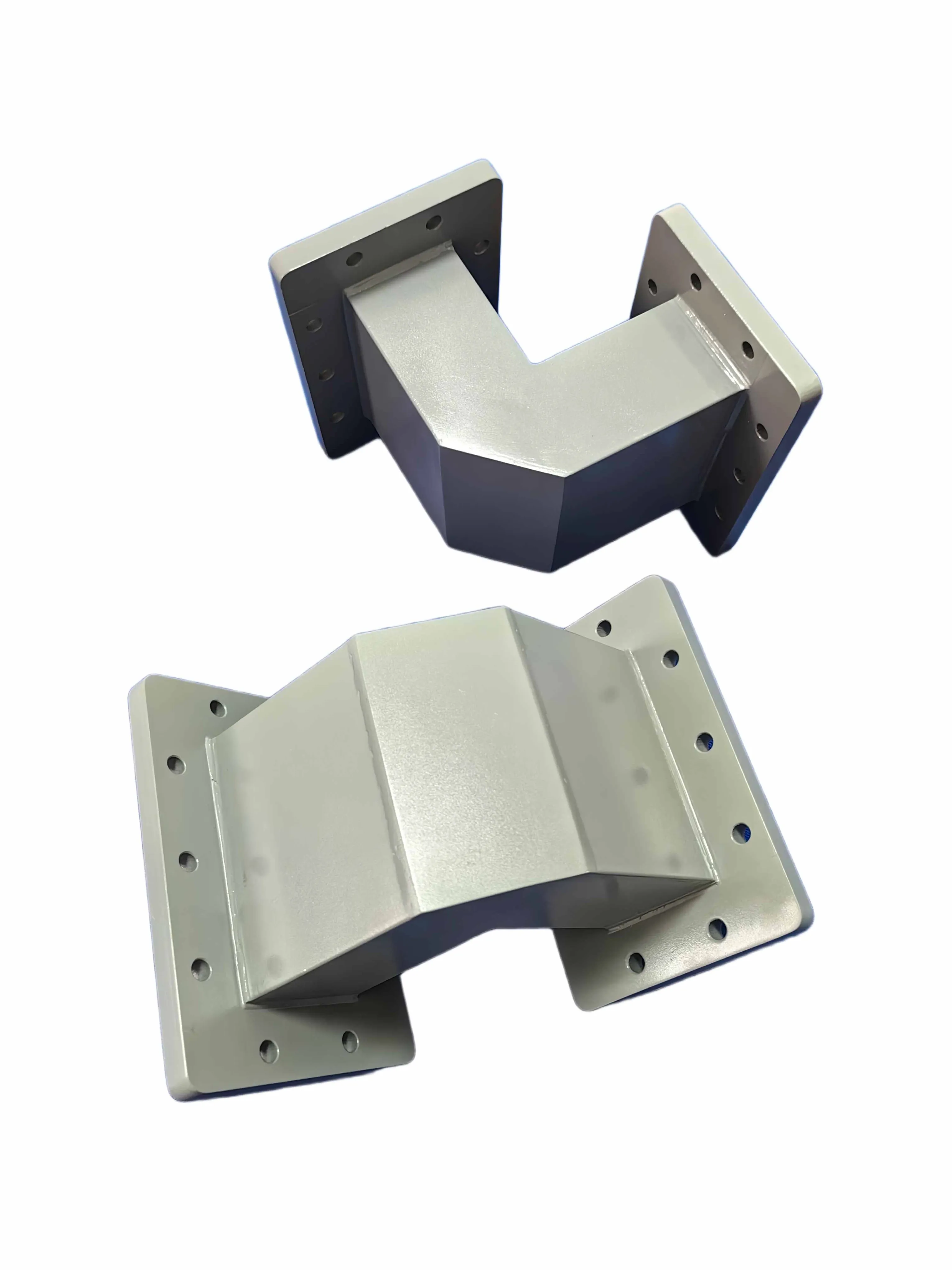
E-Plane vs H-Plane Waveguide Bends: What's the Difference, and When Does a Circular Arc Beat a Mitered Corner?
You cannot route a microwave signal the way you route a water pipe. Run a rectangular waveguide into a hard 90° corner and the electromagnetic field slams into the wall, reflecting energy straight back toward your amplifier. That is why every RF system eventually needs a waveguide bend — and why “which bend?” turns out to be two different questions.
Waveguide bends are named along two independent axes. One axis is the plane of the bend: does it curve in the E-plane or the H-plane? The other axis is the geometry of the bend: is it a smooth circular arc or a sharp mitered (corner-cut) bend? This guide separates the two so you can choose with confidence.
E-Plane vs H-Plane: Which Field Gets Bent?
In a rectangular waveguide the cross-section has a broad wall (dimension a) and a narrow wall (dimension b). The electric field runs across the broad dimension; the magnetic field runs across the narrow dimension.
- E-plane bend: curves in the plane of the electric field — it turns along the narrow wall (the b dimension). Because the cross-section rotates, a 90° E-plane bend rotates the electric-field polarization by 90°.
- H-plane bend: curves in the plane of the magnetic field — it turns along the broad wall (the a dimension) and does not rotate polarization.
If your bend feeds a polarization-sensitive stage such as an orthomode transducer (OMT) or a diplexer, an E-plane bend will twist the field orientation and must be accounted for; an H-plane bend will not.
Both bends create an impedance discontinuity that reflects some energy. To keep return loss better than 30 dB, a gradual bend needs a minimum radius greater than 1.5 guide wavelengths (1.5λg) for E-plane, and greater than 2λg for H-plane. These are the same thresholds AO Microwave applies when machining our waveguide E-bend and waveguide H-bend ranges, and they match the standard discontinuity rules described in Pozar's Microwave Engineering.
Circular Arc vs Mitered: Smooth Curve or Corner Cut?
This axis is about shape, not field orientation — and it is independent of E vs H.
A circular (radius) bend is a continuous smooth curve that gives the best return loss and the widest bandwidth. The cost is footprint: a low-reflection radius bend needs a turning radius of at least 1.5–2λg, which can be large at lower frequencies.
A mitered bend replaces the curve with a straight corner sliced at 45°, with cut depth tuned to the wavelength — about 0.2a for an H-plane miter or 0.2b for an E-plane miter. The angled face acts like a mirror, reflecting the field neatly around the corner. A well-designed miter reaches return loss better than 25 dB while occupying a fraction of the space of a radius bend, and it is cheaper to machine. The trade-off is a narrower bandwidth and slightly higher VSWR than an equivalent radius bend. If space allows, a radius bend always outperforms a miter.
For applications that need both compactness and broadband behavior, a step bend — two 45° bends separated by λg/4 — cancels the two reflections and widens the bandwidth.
The 2×2: The Two Axes Are Independent
Here is the part most catalogs obscure: E-plane/H-plane and circular/mitered are not mutually exclusive. You can have all four combinations:
| Circular / Radius | Mitered | |
|---|---|---|
| E-Plane | E-plane circular bend — smooth, low-loss turn; rotates polarization | E-plane mitered bend — compact 90° turn; rotates polarization |
| H-Plane | H-plane circular bend — smooth, low-loss; polarization fixed | H-plane mitered bend — compact; polarization fixed |
So when an engineer asks “E-bend or miter?” the honest answer is “both, depending on which wall you are turning and how much space you have.” A compact 90° turn in a tight 5G transceiver might be an E-plane mitered bend; a low-loss turn in a Satcom feed might be an H-plane circular bend. For a deeper selection walkthrough, see our guide on how to choose the right waveguide bend without sacrificing RF signal quality.
At a Glance: Comparison Tables
| Criterion | E-Plane Bend | H-Plane Bend |
|---|---|---|
| Curves along | Narrow wall (b) | Broad wall (a) |
| Polarization effect | Rotates E-field by bend angle (90° → 90° rotation) | No rotation |
| Min radius for RL > 30 dB | > 1.5λg | > 2λg |
| Best when | Vertical space is tight; polarization can be managed | Polarization must stay fixed (OMT, feeds) |
| Criterion | Circular / Radius Bend | Mitered (Corner-Cut) Bend |
|---|---|---|
| Shape | Smooth continuous arc | 45° sliced corner |
| Return loss | Best (often > 30 dB with adequate radius) | Good (well-designed > 25 dB) |
| Bandwidth | Widest | Narrower |
| Footprint | Large (needs 1.5–2λg radius) | Compact — often the only option where a radius bend will not fit |
| Manufacturing | Precise curve (CNC) | Simpler straight cuts |
Frequently Asked Questions
Q: What is the difference between an E-bend and an H-bend in a waveguide?
A: An E-plane (E) bend curves along the narrow wall and rotates the electric-field polarization by the bend angle; an H-plane (H) bend curves along the broad wall and leaves polarization unchanged. The choice affects polarization-sensitive downstream components.
Q: What is the minimum bend radius for a waveguide bend?
A: For return loss better than 30 dB, keep the bend radius greater than 1.5 guide wavelengths (1.5λg) for E-plane bends and greater than 2λg for H-plane bends. Both scale with frequency through the guide wavelength.
Q: When should I use a mitered bend instead of a radius (circular) bend?
A: Use a miter when physical space is too limited for a radius bend. With the correct cut depth (about 0.2a for H-plane or 0.2b for E-plane) a miter reaches return loss better than 25 dB. If space allows, a radius bend will always outperform a miter on bandwidth and VSWR.
Q: Do waveguide bends affect signal polarization?
A: Yes — but only E-plane bends. A 90° E-plane bend rotates the electric field by 90°; an H-plane bend does not change polarization. Account for this before connecting to OMTs, polarizers, or diplexers.
Q: How much insertion loss does a waveguide bend add?
A: A well-designed bend contributes as little as ~0.05 dB. A poorly chosen or badly machined bend can reach 0.5 dB or more per bend, and losses compound across a chain — eight bends at 0.3 dB each is 2.4 dB of avoidable system loss.
Q: Can I use a sharp 90° corner without mitigation?
A: Not in a high-frequency system. An un-mitered right-angle corner causes a severe impedance mismatch and heavy reflection; engineers use either a swept radius or a 45° miter (a “mitered 90°” is effectively two 45° bends).
Still Deciding Between E-Plane, H-Plane, Circular, or Mitered?
Send us your frequency, flange, and space constraints. Our engineering team returns a drawing and per-unit VSWR / insertion-loss test data — and we support custom specs to EIA and IEC standards — not just a part number.
Contact Our Engineering TeamSources: standard waveguide discontinuity theory (D. M. Pozar, Microwave Engineering); AO Microwave waveguide bend selection guide;
Related: Waveguide Bends Explained: E-Plane vs H-Plane, Circular vs Mitered — the two naming axes most RFQs get wrong, and the 2.4 dB mistake to avoid before it reaches the antenna.