
What Is a Double-Ridged Horn Antenna, and How Does It Cover 0.1 to 40 GHz?
What is a double-ridged horn antenna? How two internal ridges let one horn span 0.1-40 GHz, how to read the gain curve and VSWR, and where EMC and radar benches use them.
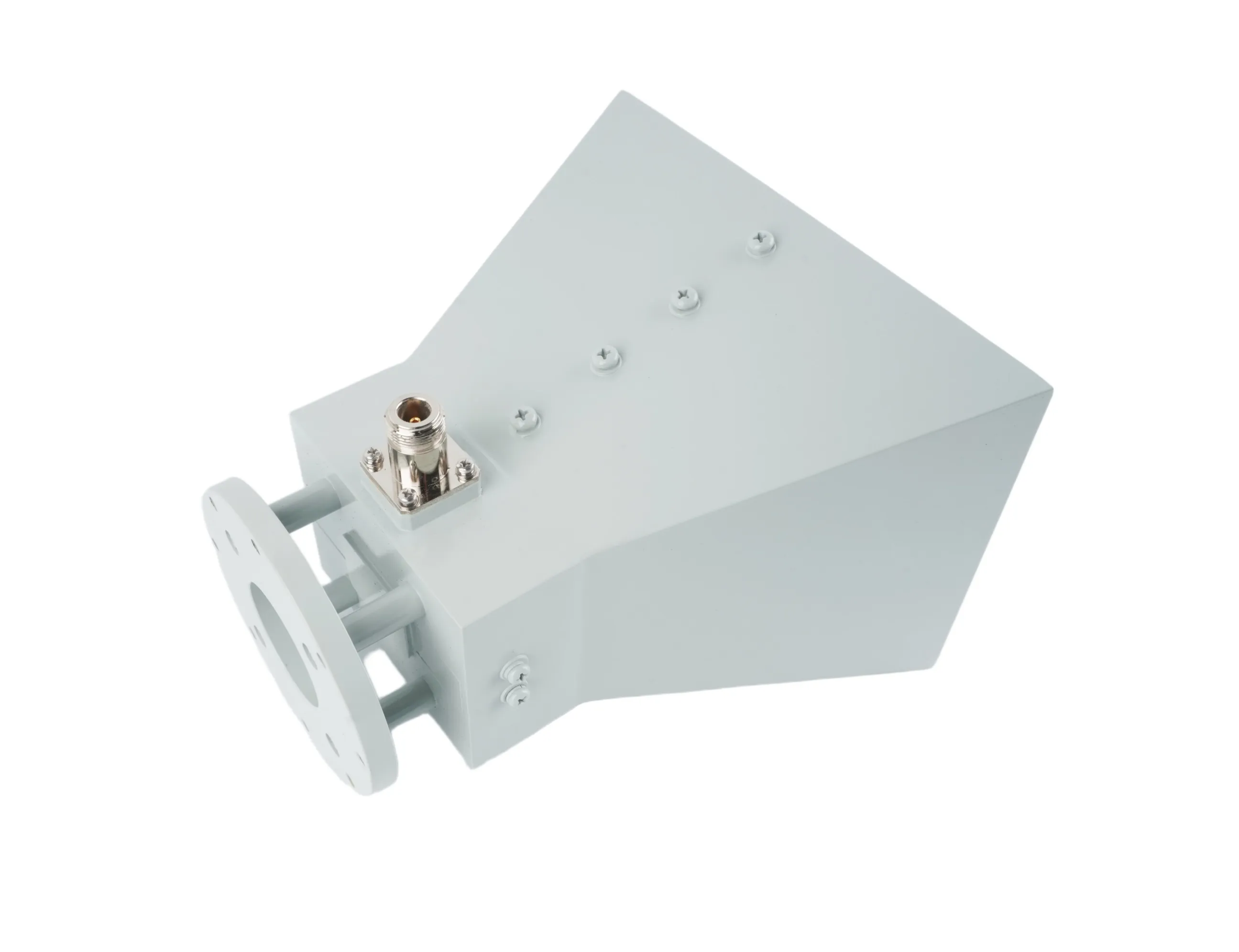
What Is a Double-Ridged Horn Antenna, and How Does It Cover 0.1 to 40 GHz?
A double-ridged horn antenna is a horn antenna with two metal ridges running along the inside of its waveguide walls. Those two ridges are the entire story. They capacitively load the dominant TE10 mode and pull its cutoff frequency down without dragging the next mode down nearly as far, so one horn keeps working in a single clean mode across many octaves instead of one. That is why the AO Microwave double-ridged horn family stretches from 0.1 GHz to 40 GHz across thirteen standard models, and why EMC labs, radar benches and EW outfits keep reaching for one when a smooth-wall horn would need a whole rack.
The Anatomy: A Waveguide, Two Ridges, One Aperture
Start at the back. A short section of waveguide feeds the horn, and inside that section two ridges run along the broad walls, tapering from full height at the throat toward the aperture. The waveguide flares into a pyramidal horn that opens into free space. Signal enters through a coaxial connector, and the transition is more deliberate than it looks: the coaxial center pin lands on one ridge and the outer conductor on the other, held by precision-machined, gold-plated contacts and rugged dielectric supports so the joint survives thermal cycling and handling.
The connector choice is not cosmetic. Type N and SMA carry the lower models, and 2.92 mm (K) takes over above 18 GHz because the smaller interface holds its mode cleanly to 40 GHz. If your test plan crosses 18 GHz, the connector decides the horn before the gain does.
Why Two Ridges Widen the Band
A smooth-wall rectangular waveguide passes its dominant TE10 mode only above a cutoff set by its width, and the next mode, TE20, appears at twice that frequency. That leaves roughly a 1.5:1 single-mode span, which is why a classic X-band pyramidal horn covers something like 8 to 12 GHz and stops.
Ridges change that arithmetic. Concentrating the electric field in the small gap between them adds capacitive loading, which lowers the TE10 cutoff. The same ridges barely move the TE20 cutoff. The gap between the two cutoffs is your single-mode bandwidth, and it opens from about 1.5:1 to something a smooth wall can never reach.
| Model family | Coverage | Single-mode span |
|---|---|---|
| 0.1-1 GHz model | One decade below the EMC band | 10:1 |
| 1-18 GHz models | L through Ku band in one horn | 18:1 |
| 0.8-25 GHz model | Sub-GHz to K band, one aperture | Over 31:1 |
There is a catch at the top of any wide band. As frequency climbs, the fixed aperture looks electrically larger, and that can excite the TE20 mode you worked so hard to avoid. The symptom is beam splitting: the main lobe squashes or splits toward the high end. Good designs manage it with precise 3D electromagnetic modeling of the ridge and flare profiles, which is how a horn holds a single-lobed pattern across the whole band instead of only where the datasheet was measured.
What the Datasheet Numbers Actually Mean
Read a wideband horn datasheet differently from a narrowband one. Three columns deserve suspicion.
Gain is a curve, not a number. On a 1-18 GHz horn the physical aperture is a small fraction of a wavelength at 1 GHz and many wavelengths at 18 GHz, so gain climbs across the band, typically from about 6 dBi at 1 GHz to roughly 18 dBi at 18 GHz. A datasheet that quotes one average gain figure is telling you the middle of a range. Ask for the gain curve, and ask specifically about the low edge, because that is where your field strength is thinnest.
VSWR has a max and a typical. Most models in the family specify 2.5:1 maximum across the band, the 1-18 GHz and 1-20 GHz models hold 2.0:1, and the 18-40 GHz models typically run better than 1.50:1. A maximum is a guarantee you can design against; a typical is what you will usually see. If your link budget needs a number at the worst frequency, use the maximum.
Beamwidth is two numbers. E-plane and H-plane 3 dB beamwidths are listed separately, and they diverge as frequency rises. The 1-18 GHz horns open from about 30 to 80 degrees; the 18-40 GHz models tighten to 10 to 20 degrees. That divergence decides how uniformly you can illuminate a chamber, which matters more than peak gain.
| Spec column | What to check before you buy |
|---|---|
| Frequency range | Your lowest frequency, not your highest, eliminates most of the catalog |
| Gain | Curve or point? Average, minimum, or at the band edge? |
| VSWR | Max across band or mid-band best case; reflected power follows from it |
| Beamwidth | E and H plane at your highest test frequency |
| Calibration data | Gain and antenna factor against frequency, tied to the serial number |
Reading an AO Microwave Model Number
The part number carries the specification, which makes cross-checking a datasheet fast. Take AO1G18G-DRHA10NK: 1-18 GHz coverage, DRHA for double-ridged horn antenna, 10 for average gain in dBi, and NK for an N female connector. Swap the suffix to SK for SMA female or 2.92K for 2.92 mm. The gain digits work the same way across the family, so DRHA8, DRHA15 and DRHA16 parts deliver 8, 15 and 16 dBi class performance respectively.
| Part number | Coverage | VSWR max | Avg gain | Connector |
|---|---|---|---|---|
| AO0.6G6G-DRHA10NK | 0.6-6 GHz | 2.5:1 | 10 dBi | N female |
| AO1G18G-DRHA10NK | 1-18 GHz | 2.0:1 | 10 dBi | N female |
| AO8G40G-DRHA152.92K | 8-40 GHz | 2.5:1 | 15 dBi | 2.92 mm female |
| AO18G40G-DRHA162.92K | 18-40 GHz | 2.5:1 | 16 dBi | 2.92 mm female |
Where Double-Ridged Horns Earn Their Keep
EMC compliance testing. IEC 61000-4-3, the radiated immunity standard most commercial products eventually face, historically spans 80 MHz to 6 GHz at levels from 1 V/m to 30 V/m, with defined coverage at 800-960 MHz and 1.4-6.0 GHz to prove immunity to digital radio telephones. A 0.6-6 GHz horn covers that entire legacy range from one aperture, and the 1-18 GHz models push well past it for the 2020 edition of the standard, which removed the upper frequency limit.
Radar target simulation. A wideband horn illuminates a target across the full bandwidth of the chirp, so the returned signature is not stitched together from several narrowband measurements.
EW direction finding. Wide instantaneous coverage with a stable pattern lets one antenna serve a band that would otherwise need a switching array of narrowband horns.
Antenna and chamber measurement. Where the job is generating or collecting a field rather than defining a gain reference, the double-ridged horn does the work and a calibrated unit supplies the traceability. For compliance work that traceability runs through ANSI C63.5, which covers antenna calibration from 9 kHz to 40 GHz, alongside IEEE-291 and CISPR 16 practice. If you are matching a horn to a specific band and standard, the double-ridged horn antenna selection guide walks the same decision band by band, and the RF frequency bands table maps the letter bands to the waveguide sizes behind them.
Frequently Asked Questions
Q: What is a double-ridged horn antenna used for?
A: Anywhere one antenna has to generate or receive across many octaves: EMC radiated emissions and immunity testing, radar target simulation, EW direction finding, satellite ground test and general RF measurement. The ridges buy bandwidth, and bandwidth is what keeps a bench from needing a drawer full of narrowband horns.
Q: Why does gain increase across the band?
A: The aperture is fixed, so as wavelength shrinks the aperture spans more wavelengths and directivity rises. A 1-18 GHz horn typically climbs from about 6 dBi at 1 GHz to roughly 18 dBi at 18 GHz. Plan your field strength and amplifier budget around the low edge, not the average.
Q: What VSWR should I expect from a double-ridged horn?
A: Most models specify 2.5:1 maximum across the band, the 1-18 GHz and 1-20 GHz models hold 2.0:1, and the 18-40 GHz models typically measure better than 1.50:1. Treat the maximum as the design number and the typical as what you will usually see on the bench. The VSWR and return loss table converts those figures into reflected power.
Q: Can one double-ridged horn both transmit and receive?
A: Yes. These are linear polarized, reciprocal antennas, so one horn serves radiated emissions as a receiver and radiated immunity as a transmitter. Check power handling before planning a high-level susceptibility test, because peak power is limited by the coaxial connector and its transition probe rather than by the horn itself.
Q: Why do 18-40 GHz models use 2.92 mm connectors instead of N or SMA?
A: Connector families have frequency limits that are easy to overlook. Type N is commonly used to around 11 to 18 GHz and SMA to 18 GHz, while 2.92 mm (K) is rated to 40 GHz. Above 18 GHz the 2.92 mm interface is the practical choice, and because it is mechanically smaller, mating torque and cable strain matter more than on a Type N bench.
Q: Do I need calibration data with a double-ridged horn?
A: For compliance work, yes. Ask for gain against frequency and antenna factor data tied to the serial number, covering the full band you will use. ANSI C63.5 defines that calibration from 9 kHz to 40 GHz. Without the data you can still make relative measurements, but you cannot defend an absolute field strength in a report.
Choosing a Double-Ridged Horn for Your Bench?
Tell us the lowest frequency you must cover, the field strength or measurement you need, and the connector your system expects. We will confirm the model, the gain curve and the calibration data, and return a datasheet within 24 hours.
Contact Our Engineering Team