
How to Specify a Waveguide Limiter: Spike Leakage, Flat Leakage, Recovery Time, Power Handling
Specifying a waveguide limiter: flat leakage, spike leakage, recovery time, and power handling against your LNA and pulse. Quotes in 24 hours.
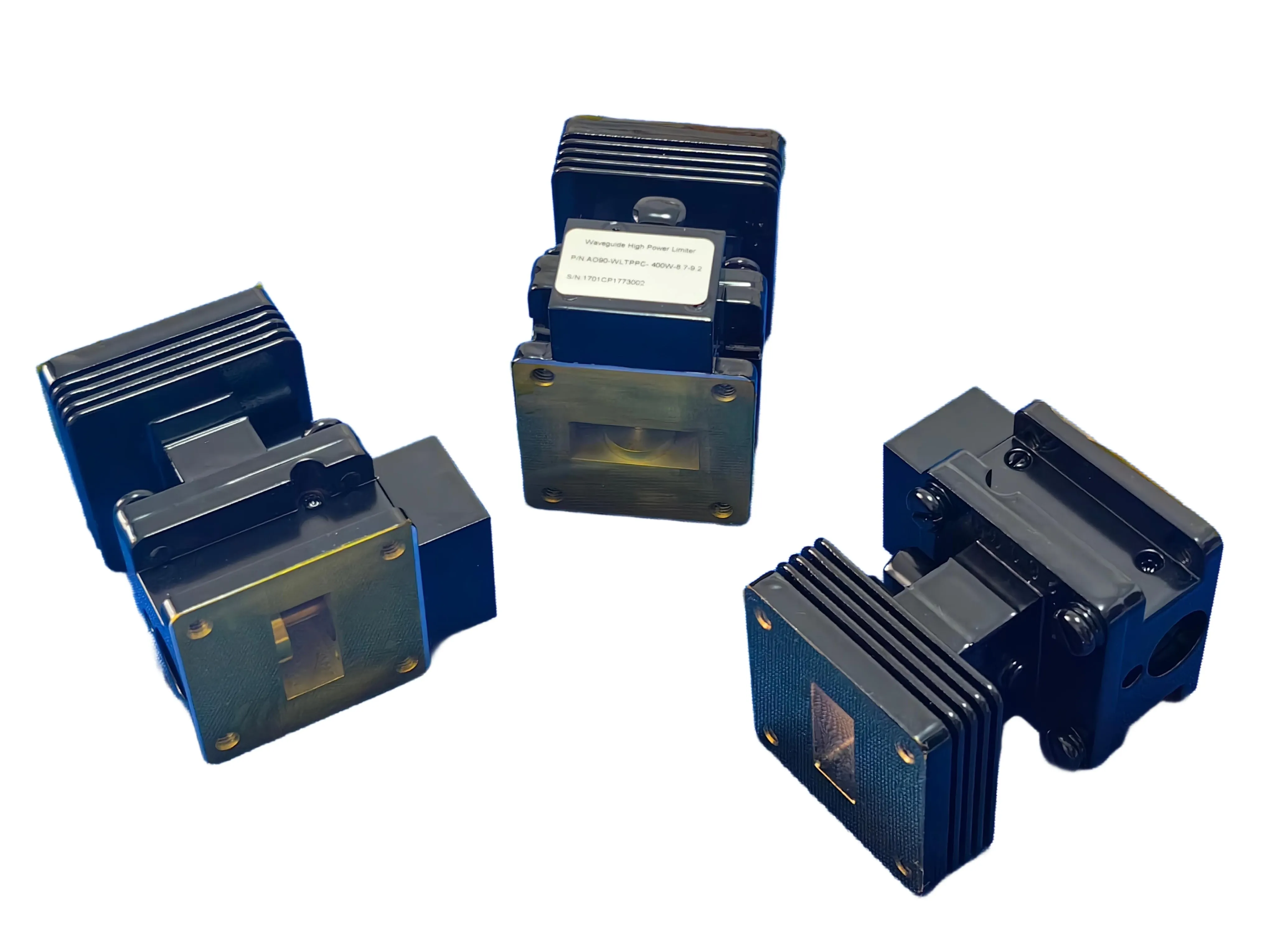
You have decided you need a limiter — not an isolator, not a circulator, but a device that actually clamps an incoming high-power pulse before it reaches your LNA (if you are still weighing which device, our limiter vs circulator vs isolator guide lays out the difference). The next question is harder: once you open a datasheet, which numbers decide whether the part saves your receiver or silently lets it cook?
Four parameters carry almost all of the risk: flat leakage, spike leakage, recovery time, and power handling. Get any one of them wrong and the limiter passes its bench test while failing your real pulse conditions. Here is what each one means and how to read it.
Flat Leakage: The Number That Protects Your LNA
After a high-power pulse arrives, the limiter conducts and holds the receiver side at a steady, bounded level. That steady level is flat leakage. For a PIN-diode limiter it is typically in the +20 to +30 dBm range (about 0.1 to 1 W), consistent with standard PIN-diode limiter references from MACOM and the Skyworks PIN Limiter Design Guide. Your LNA must tolerate that level continuously for the duration of the pulse — so flat leakage has to sit safely below your LNA's maximum input rating, with margin.
Lower is better, but there is no free lunch: pushing flat leakage down often trades against insertion loss and power handling. The right target is "below your LNA's damage threshold with comfortable margin," not "as low as physically possible." For the underlying clamping principle, see our pillar guide on how a waveguide limiter works.
Spike Leakage: The Part That Bites Before the Diode Wakes Up
A limiter is not instantaneous. In the first tens of nanoseconds after a fast-rising pulse hits, the PIN diode has not yet fully conducted, so a brief, higher spike of power gets through before limiting engages. That transient is spike leakage, and it is always higher than flat leakage. It is characterized by two numbers: its amplitude (dBm) and its width (ns).
Engineers get burned here: a limiter can show excellent flat leakage yet still emit a nasty spike that exceeds the LNA's instantaneous rating for a few nanoseconds. Read both numbers. If your LNA's survivable peak is, say, +30 dBm for 10 ns, a spike reaching +38 dBm for 15 ns is a failure even if flat leakage is a comfortable +22 dBm.
Recovery Time: The Blind Window Between Pulses
When the pulse ends, the diode must return to its transparent (low-loss) receive state. The time it takes is the recovery time. During recovery, the limiter's insertion loss is elevated and its protection is reduced. For self-biased PIN limiters, recovery typically lands in the tens of nanoseconds to around a microsecond range, longer for higher peak power or longer pulses.
Why it matters for radar: recovery time must be shorter than the pulse repetition interval (PRI). If it is not, two things go wrong at once — your next returning echo is attenuated (you lose sensitivity), and the next transmitted pulse may not be clamped (you lose protection). Specify recovery time against your actual PRI, not a generic "fast" claim.
Power Handling: Peak vs Average, and What "Survives" Means
A limiter specification needs two power numbers, and they are not the same thing:
- Peak (pulse) power handling — the incident pulse the limiter can clamp without damaging its semiconductor elements. Radar incident pulses can be kW to MW-class, but because the limiter holds the receiver side to roughly 1 W, the limiting elements absorb the difference. They must be rated for that incident peak.
- Average power handling — the continuous heat the limiter can dissipate. This is set by pulse width and duty cycle, not by peak alone.
Always ask for both ratings at the pulse width and duty cycle you actually run. A limiter that survives a 1 µs pulse at 0.1% duty may fail the same peak at 10% duty because the average heating is a hundred times higher. AO Microwave specifies waveguide limiters across the standard bands — WR90 (X-band), WR62 (Ku-band), and others — against the customer's real pulse conditions rather than catalog-typical numbers.
The Spec Sheet, Decoded
| Parameter | What it is | What to specify | Why it matters |
|---|---|---|---|
| Flat leakage | Steady leakage after limiting engages | dBm, below LNA rating | Defines continuous stress on the LNA |
| Spike leakage | Initial transient before clamping | Amplitude (dBm) + width (ns) | Worst-case instantaneous stress |
| Recovery time | Return to low-loss receive state | ns, shorter than PRI | Sensitivity + next-pulse protection |
| Peak power | Clamp without damage | kW/MW + pulse width + duty | Element survival |
| Average power | Continuous dissipation | W at your duty cycle | Thermal margin |
| Insertion loss | Loss to the wanted signal | dB, as low as practical | Receive sensitivity |
The limiter turns a kW–MW incident pulse into a brief spike followed by a bounded flat-leakage level the LNA can survive.
A 60-Second Selection Checklist
- Know your LNA's max input. Flat leakage must sit below it with margin — this single comparison rules out most mismatches.
- Know your pulse. Peak power, pulse width, and PRI set the spike-leakage, recovery-time, and power-handling requirements.
- Pick your band. WR90 (X-band), WR62 (Ku-band), or another EIA size to match the receiver — see the limiter vs circulator vs isolator comparison for the full picture.
- Ask for measured numbers at your conditions. "Typical" at mid-band is not "qualified at your pulse." Request data at your actual peak, width, and duty cycle.
Frequently Asked Questions
Q: What is the difference between spike leakage and flat leakage?
Flat leakage is the steady level the limiter holds once it has engaged — typically +20 to +30 dBm for a PIN-diode design. Spike leakage is the brief, higher transient in the first tens of nanoseconds before the diode fully conducts. Both must stay within your LNA's ratings; a good flat number does not excuse a bad spike.
Q: Why does recovery time matter for radar receivers?
Recovery time is how long the limiter takes to return to its low-loss receive state after the pulse ends. If it exceeds the pulse repetition interval, the next echo is attenuated and the next transmitted pulse may not be clamped. Recovery time must be shorter than your PRI.
Q: What power-handling numbers do I need to specify?
Two: peak (pulse) power the limiter can clamp without damage, and average power it can dissipate continuously. Always give them at your real pulse width and duty cycle — the same peak at a higher duty cycle can multiply the thermal load (0.1% to 10% duty is 100x the average power) and exceed the limiter's rating.
Q: How low should flat leakage be?
Low enough to stay below your LNA's maximum input rating with margin. For most receiver front ends, the +20 to +30 dBm range from standard PIN-diode designs is acceptable; pushing lower trades against insertion loss and power handling, so target "safe margin," not "minimum possible."
Q: Does a limiter add insertion loss to my received signal?
Yes, a small amount. A self-biased PIN diode is nearly transparent at low signal levels, so receive-band insertion loss is typically low (fractions of a dB to a couple of dB depending on band and power rating), but it is a real parameter to account for in your link budget.
Q: How do I know if a stock limiter fits my waveguide band?
Match the EIA waveguide size to your operating band: WR90 for X-band, WR62 for Ku-band, and so on. If your frequency, pulse, or leakage requirement is outside a standard configuration, the limiter is a custom build — which is normal for receiver-protection parts. See the limiter vs circulator vs isolator comparison for band context.
Specifying a Receiver-Protection Limiter?
Send us your band, pulse peak, width, duty cycle, and LNA max input. We will confirm whether a standard configuration for your band fits — and quote within 24 hours.
Contact Our Engineering Team